Router Plane

Showing posts with label Sanding Block. Show all posts

Monday, January 10, 2022

Sanding Block - #5 Completing Knobs, Danish Oil Finish & Done

This post is a little longer that most because at the end I have included the sequence of operations including material and hardware sizes.

After turning the knob blank to a cylinder, marking the beginning point of the dome and the blank’s overall length the blank is turned down to final length.  With that done the dome part of the knob is turned.

Adding the six faces to the cylinder is next.  It did take a while come up with a process to get them the same size and 60 degrees apart.  First, a jig is needed to hold the knob in place while the face is made and second the jig has to be able to control the rotation of the knob (60 degrees) so the next face is in the proper orientation.  The top photo below shows the top of the jig.  On the right is business end that controls the location of the cut and its depth.  The hole is for the threaded rod while the partial hole on the left is where my thumb sets to control the depth of cut.  The bottom photo is the back side.  You can see where the threaded rod comes through.  A nut is used to tighten the rod which holds the knob in place.  The recess allows the threaded rod to be below the face of the jig.

Next the knob is mounted in the jig as shown in the top photo.  The bottom photo shows the first face completed.  I will show the jig in use and how the faces are made in just a bit.

With the first face made the nut holding the knob in place is loosened and the knob rotated 60 degrees clockwise.  The first face is now parallel to the long reference edge of the jig at the bottom of the photo.  The nut is tightened to hold the knob in place and the second face is made.  This is shown in the top photo.  This process is repeated to make the third face as in the bottom photo and continues until all six faces are made.

Here in both photos all six faces have been made.  The bottom photo is simply a different view of the knob and jig.

Now with an idea of how the knob and jig work together the only thing left out is to explain how the faces get made.  Of the options available using the disk sander seemed to make the most sense to me as the rate and amount of material removal is easily controllable.  The photo shows sander with the miter fence set so the jig presents the to be made face parallel to the disk.  In use the miter fence is moved back and forth to prevent the disk from burning the wood while the jig is gradually fed into the disk until the proper depth is reached. 

After the six faces are finished, they need to be sanded since the grit on the disk sander is certainly not smooth enough.  To maintain the flat face at the proper angle the knob is set in another jig and each face is sanded with 220 and 320 grit sandpaper to remove all traces from the disk sander. 

The last two bits of work on the knob is first to remount it on the lathe then hand sand to ease the transition between the dome and the faces then do the same thing with the sharp points between faces.  When done with the 320 paper the lathe gets reversed and the rounded edge between the faces gets sanded to make the feathering even on both sides.   Last the piece is removed from the jig and the edge between the faces and the base of the knob gets softened with sandpaper.

Everything went well except for the last knob.  When it was turned down to the cylinder, I saw a faint crack in the blank.  I had hoped that it would get turned away as the piece was cut to length and domed but no such luck.  The straw that broke the camel’s back was when the first face was made.  There right across the face was the crack that probably ran most of the way through the piece.  Not what I wanted but so it became scrap and another one made.  Looking back the knobs were the hardest most time-consuming part of the build as they were all made individually with little benefit of reusable machine setups. 

Below is what the five sanding blocks look like ready to apply three coats of Danish Oil Finish and buff out.  This type of finish is used rather than my usual lacquer as an oil finish can be rejuvenated down the line a lot easier than a film finish. 

Here are the pieces with one coat of Danish Oil Finish on them.  There are seven knobs because I made one to replace the prototype and ended up finishing the cherry one with the crack.
With all three coats of Danish Oil completed the cork bottom needed some attention.  No matter how careful when applying the finish invariably I got some on the cork.  The top photo is typical of what happened.  As I wanted to have an unfinished cork bottom it needed to be fixed.  Cleaning is pretty easy. a sheet of 220 grit sandpaper is clamped down to the table saw extension and a few passes cleans it up as shown in the bottom photo.

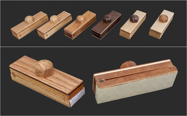
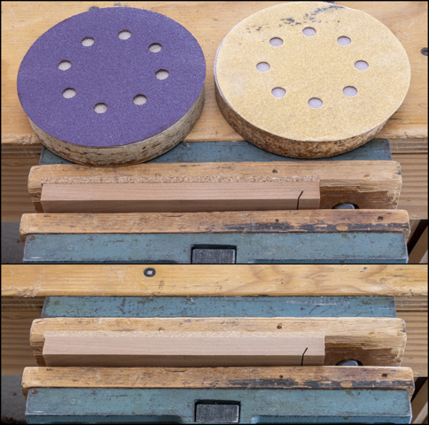
The top photo shows the five completed sanding blocks plus the prototype finished with the final buff done.  The bottom photo has two of the blocks with sandpaper loaded on them.  I know this project may seem like overkill for sanding blocks but I like working with nice tools and enjoyed the build. 

Once completed I built a storage case to hold them along with some cut sandpaper.  Five of the blocks are loaded with different grits of sandpaper from 80 to 400 grit.  In general, the darker the sanding block the finer the grit.  In addition, I wrote the grit on the end of the sandpaper.  This is what it looks like and will get mounted on the peg board for easy access. 

Early on I wondered if the parts would be interchangeable between the six blocks.  After giving it a try they are and if desired, the parts could be all mixed up and still work just fine.  Don’t think I will do that as I like the continuity of the woods but it is interesting that it would work.

For anyone who wants to make these here is the sequence of operations along with material sizes I used.

Sanding Block Sequence

  1. Thickness two blanks 2” x 7” x ½”
  2. Thickness two blanks 2” x 7” x 1/8” (one contrasting)
  3. Glue thin blanks to upper base
  4. Cut angled notch in lower base
  5. Glue cork to lower base
  6. Cut glued stack and lower base to 6.25” length and 1.83” width
  7. Sand cork on lower base to 5/8” total thickness and sand smooth edges
  8. Clamp upper and lower bases together, drill 5/16” dowel hole centered 13/32” from edge
  9. Turn 5/16” dowel
  10. Using dowel for registration drill 5/16” hole vertically through stack and just into base for ¼” rod
  11. Countersink underside of stack with ½” Fostner bit 1/8” deep
  12. Drill 10 mm hole in base for insert & chamfer
  13. Temporarily install ¼"-20 brass insert & remove
  14. Finish sand base upper face
  15. Glue in dowel
  16. Sand excess off dowel ends
  17. Epoxy insert in place
  18. Route top edges of stack
  19. Final sand top stack
  20. Finish using DOF

Sanding Knob Sequence

  1. Layout knob blanks, 1 5/8”+ diameter with compass.  Drill 7/32” hole 5/8” deep for rod.
  2. Bandsaw knob to rough circle
  3. Cut 1¾” long ¼”-20 threaded rod
  4. Thread knob hole & epoxy rod into knob blank
  5. Put fixture in lathe and use live center to true center
  6. Do not take fixture out of lathe, take chuck & fixture off lathe then put cap in fixture
  7. Turn to a 1 37/64” diameter cylinder
  8. Turn dome shape total 7/8” tall with lower ½” still a cylinder
  9. Take chuck off lathe, remove knob & install in jig
  10. Sand 6 flats with jig on disk sander, remove from jig
  11. Use sanding jig to sand flats to 320
  12. Put back on lathe fixture then using 120, 220 & 320 sandpaper feather dome & edges between flats knocking of sharp edges.  At very end reverse lathe and sand with 320 to help feather both edges
  13. Remove from lathe fixture and break base to face surface


Monday, January 3, 2022

Sanding Block - #4 Installing Insert, Gang Routing & Knobs Part 1

Final sanding of the top of the base using 220 grit sanding paper is next.  That’s followed by gluing and clamping the dowel in place in the photos below.

After the glue cures the dowels which are just a tad long are sanded flush with the base.  The large disk sander with a guide to keep the base square with the disk is used.  That’s followed by sanding the sides and ends down to 220.

With the dowels flushed to the sides and all sides finish sanded the brass insert can be epoxied in place.  A small amount of the epoxy is spread on the sides of the hole in the base.  The insert is run in with the ground off end put in first until it bottoms out.  That’s done using a short bit of threaded rod that has a couple of jam nuts on it chucked up in a drill. 

Below in profile you can see how the insert sticks up above the top of the base and that’s why earlier a countersink was added to the underside of the top.  Without it the top wouldn’t be able to clamp down on the sandpaper holding it in place.

While the epoxy cures the 3-layer top stack gets its top edges and corners rounded over for a softer feel in the router with a 1/8” radius bit.  The corners get done first because they are end grain which is prone to chipping when the router bit exits the cut.  That’s solved by using a scrap backup piece.  Another consideration is that the pieces will be on their narrow edge when routing and could be prone to tipping which is solved by clamping it to a wide block for stability.  Clamping to the wider block also helps guide the piece across the router bit as the opening in the fence is wider than the piece.  I did add a second larger push block to the right to provide some additional stability for peace of mind.  It worked well on the single prototype so when routing the rest they all got clamped together and routed in one pass.  The setup below shows everything ready to go.  The long edges are easy to route using a push block to keep my fingers away from the bit.  Once routed all the surfaces get sanded. 

When I did the prototype the knob that clamps the sandpaper in place is domed as in the photo below on the left.  It was acceptable but I wanted a shape that provided a better grip and felt good in palm of my hand and didn’t want any sharp edges.  Lots of ideas came to mind but all had one or more flaws.  A shape that did occur to me in the middle of the night is similar to what’s called an Acorn nut shown on the right.  With that shape in mind, it’s back to the prototype stage figuring out how to make a domed hexagon.  Once I got a finished prototype it’s time to make five more.

The process starts by laying out a 1 5/8” diameter for the knob with a compass.  Here are the oak, cherry and walnut blanks to be used.

Next, it’s over to the bandsaw to cut the rough knob blanks out.  The bandsaw has a ½” wide blade on it which is too wide to make a 1 5/8” diameter cut.  If I changed it out to a ¼” one there would be a lot less burning and a smoother cut since a ¼” blade can cut a tighter radius.  However, it takes a while to change the blade and adjust the six blade guides.  Besides these are all going to be turned round on the lathe so it’s not a big deal.

After rough cutting the blanks out on the bandsaw a 7/32” hole 5/8” deep is drilled for threaded rod.  The 7/32” diameter is a little odd size but it is just slightly less than the diameter of the ¼” threaded rod.  I do that so some shallow threads get cut into the knob when doing the initial install of the rod.  That’s done by using the drill press, rotated by hand, to make sure the rod is square and true to the underside of the knob.  That's so when it gets tightened the knob lays flat against the top of the sanding block.

Sizing a section of threaded rod that will get epoxied in the knob is next.  The procedure is a little more involved than just using a bolt cutter or hack saw to cut the rod to length.  Either one of those damages the threads at the cut making it hard to start in the brass insert and I want the rod to easily start and have no sharp edges at the cut.  The photo below shows the threaded rod clamped in place with a piece of tape marked with the 1¾” length needed.  On the left is a ¼-20 die that will be used to chase the threads after the cut.  Also, in the background you can see three finished pieces ready to be epoxied in place.

This is after the rod has been cut and you can see the resulting burr on both pieces.  From here the long rod is removed from the clamp, the rough end ground smooth and the die spun off the rod to reform the threads.  Last, the short section of rod to be used gets its end cleaned up by grinding the rough end smooth then running the die from the good end to reform the threads.

Next the sized threaded rod is epoxied in the cap place making sure 1 1/16” of rod is exposed.  A pair of jamb nuts and a wrench lets me run them in.

After the epoxy cures overnight the cap assembly is threaded in a lathe fixture made specifically for this purpose and a nut is put on the threaded rod from the inside locking the assembly in place.  The top photo shows the rough blank mounted and the bottom one it turned down to a cylinder.  The left white line is where the dome part of the knob starts and the right line is the overall height.

In checking there was a problem with one knob where the end of the blank was not square with the threaded rod.  No idea why but it did need to be trued up so it will lay flat on the sanding block’s body when tightened.  Fortunately, it was not hard.  Below shows the lathe setup.  From the left a drill chuck clamps onto the threads but not so tight that it deforms them.  Next is a couple of jamb nuts on the threaded rod that are tight to the jaws of the chuck.  To the right of the knob is the lathe’s tail stock.  It has a live center mounted in it that applies pressure against the knob which gets transmitted to the jamb nuts providing enough friction against the chuck that the face can be turned true.  That’s as long as the tools are sharp and a light touch is used.

Next Up – Completing Knobs, Danish Oil Finish & Done

Monday, December 27, 2021

Sanding Block - #3 Drilling Concentric Holes, Turning Dowels & Brass Inserts

With the fence distance set to center the drill on the joint between the base and upper stack another stop is added.  Its location is found using the center finder to set the left/right location.  Here the stop has been set, the center finder removed and the drill installed.  Not shown in the photo is a depth stop set so the bit just breaks through into the piece of plywood under it.

The photo below shows the result, a half circle cut in the top and base.

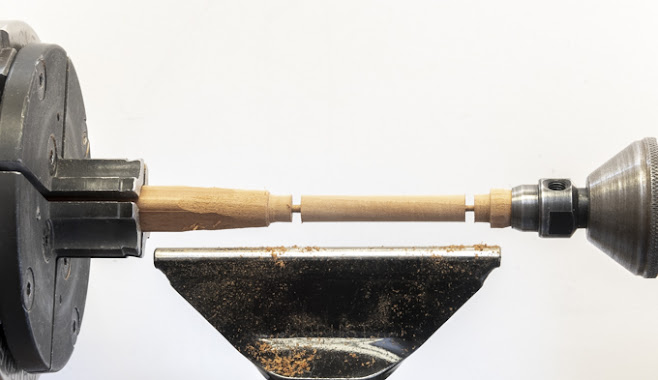
The next step is to make the dowels that will get glued into the base later on.  The top photo shows the dowel and where it will be glued in the base.   I will be making the dowels because I want them to be made out of a matching material and because the need to fit perfectly where they go.  Making them starts out with a ½” square blank which is about the smallest size that will fit in my lathe’s chuck and about a foot long.  There is a problem with trying to turn a foot long piece down to a 5/16” dowel.  Turning a piece that long and narrow is not all that rigid so when turning it can flex and chatter or generate sympathetic vibrations.  Both prevent a getting a smooth circular dowel.  The fixes available to are to either cut the blank down into shorter pieces or insert it through the hollow spindle in the lathe headstock.  A steady rest can be bought that uses wheels in frame to put pressure on the blank but I don’t have one.   Fortunately, my lathe has a hollow spindle unfortunately, it’s 5/8” in diameter and you can’t put a ½” square blank though a 5/8” hole.  Almost but not quite.  That brings me to the bottom photo which shows where I rounded the corners of the blank using a 1/8” router bit.  That’s all it took to make it fit.

Here is what the blank looks like mounted in the 4-jaw chuck on the lathe.  After mounting I turned the end to small rounded nub which will get used next.  Note how there is not much of the blank sticking out of the chuck so as to minimize any flexing. 

With the nub turned the blank is extended out so it’s just longer than my shortest tool rest and set into the live center in the tail stock.  This live center has a removable center pin which when taken out leaves a cup that the nub fits in.  With the blank supported at both ends and being fairly short the chance of having problems during turning is greatly reduced.

After turning the blank to a rough cylinder, I use a 3/8” wrench as a guide then using a parting tool shave the cylinder down until the wrench just slides over it giving me a 3/8” diameter reference point.  The same thing is done at each end of the dowel then the excess is turned down flush.  Now I have a 3/8” constant diameter cylinder and only have to take off a little more to get to the finished dowel diameter.

Last, a thin parting tool is used to cut the finished dowel off about 1/8” long.  Here that’s almost done.  When parted free a little sanding cleans up the ends.

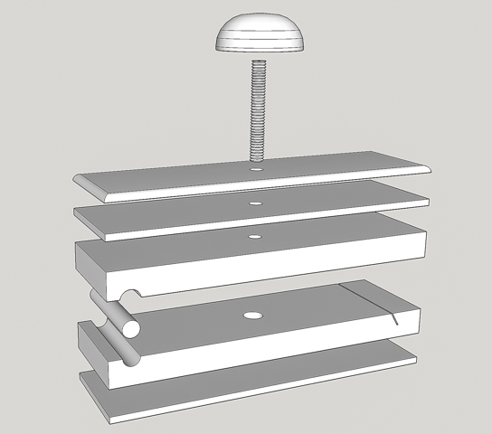
Next are four separate drilling operations for the Knob and threaded rod that will lock the sandpaper in place.  Here is a drawing showing most of the finished holes.

First, with the dowel in place, shown with the arrow at left end of sanding block, for registration of the base and 3-layer stack the center finder is used to pinpoint the hole’s location.  As before the fence is set and a stop block is added so the 5/16” hole gets drilled in the same place in all the sanding blocks.  The hole goes only through the 3-layer stack and just into the base.  That’s so the brad point drill leaves just a tiny dimple in the base which will be use to locate a different hole later on.

Second, the underside of the top 3-layer stack gets a 1/8” deep counter sink made using a ½” diameter Fostner bit.  By carefully making sure the original hole is centered in the piece I can flip the 3-layer stack over and using the same stop block/fence setup get a countersink concentric to the original hole.  The reason for the countersink will be covered later.
Third, without moving the stop block/fence setup the base is set back in its original position.  A 10mm bit is installed to drill a hole for the threaded insert.  If everything has gone right the tip of the bit should align exactly with the dimple from the hole drilled in step one.  Before drilling the depth stop needs to be set so the point of the drill stops right before it goes into the cork.  Good news is the alignment was right on for all the five bases.

Fourth and last the 10mm hole in the base gets a small chamfer cut.  This is to ease the entry of the threaded insert as it is installed preventing splintering at the starting point.

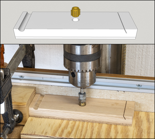
Temporarily installing the threaded insert in the base is next.  The insert (top photo) is made out of brass and has a wood thread on the outside while the inside has a ¼”-20 machine thread.  This allows the threaded rod that’s part of the knob assembly to be put in and taken out frequently without stripping out the wood.  The bottom photo shows the insert being installed.  The drill press is used to make sure it starts square and plumb.  A critical point is to use your hand to turn the chuck to install the insert and NOT I repeat NOT turn the drill press on to screw the insert in.  If you do that, things will go bad in a hurry not ending up well at all!  An added bonus is being able to use the stops already set up to locate the base.

In this closeup the wood threads are visible on the outside of the insert.  The multiple nuts on the inserting shaft are used to put more friction between the insert and the bottom nut than between the insert and the base so the insert can be removed.  Once run in the insert is removed to be installed later.

Because the insert it taller than the base I need to grind it down some.  The photo on the left shows one before grinding and the one on the right after grinding which will be installed shortly.

Next Up – Installing Insert, Gang Routing & Knobs Part 1

Monday, December 20, 2021

Sanding Block - #2 Angled Cut, Cork Base, Final Sizing & Locating Dowel

Cutting the 60-degree angled notch in the base that holds the sandpaper is next.  That’s shown circled in red on the completed prototype.

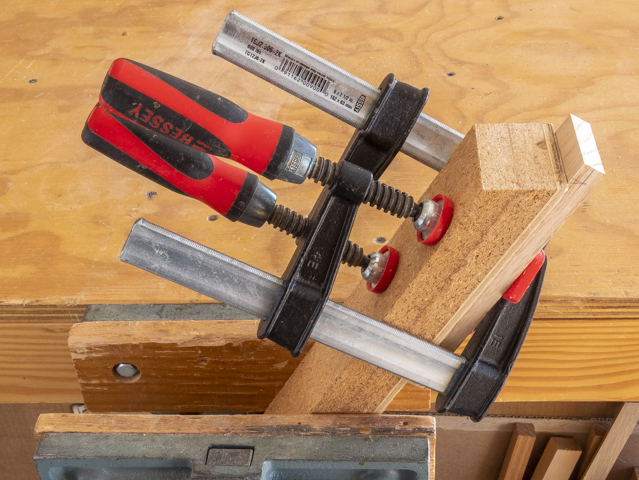
To make the cut a laminated MDF and ¼” plywood block leftover from another jig is cut at a 60-degree angle on its end.  This is clamped in the bench vice with the 60-degree cut parallel to the floor so I am working on a horizontal level surface.  It will act as a guide while I hand saw the slot with a thin Japanese pull saw.  Once the cut is laid out the base is clamped to the guide as shown in the photo below. 

Here is a close-up of how that looks.

With the base clamped in place the Japanese pull saw is laid flat on the beveled guide.  It is held in place by two of my fingers lightly pressing down on the blade as I saw cut the slot.

Once the first piece is cut it’s used as a template to mark the rest of the bases.  That’s done by clamping a framing square to the workbench, setting the template in place then adding the next piece to be cut adjacent to it and using a square draw a line where the cut gets made.

To make sure the base is parallel with the angled jig a scrap is temporarily clamped to the jig to act as a stop, the to be cut base held tight to it, the pencil line for the slot aligned with the end of the jig and the base clamped to the jig.  Here that’s all been done.  Next the temporary stop gets unclamped, removed and the cut made.  The saw is on the workbench ready to go.

This closer view shows how the pencil line for the slot gets lined up with the end of the jig.

Gluing the cork onto the base is next.  Below is the stack of the slotted bases and the stack of cork that has already been cut.  The glue-up process is the same as when the three layer tops were glued together earlier so I won’t go through that again.

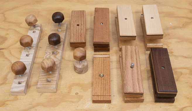
Once the cork/base glue joint has cured overnight the best long edge of it and the three-layer top part gets sanded with 80 grit paper and then 120 grit. The top photo shows the 80 and 120 grit sanding disks with the unsanded cork/base part.  The bottom photo is after sanding.   This one sanded edge is to make sure there is a nice straight smooth edge to work off of when ripping to the final width.  That’s done on the table saw in two passes.  The first pass is done by placing the good edge up against the fence so the opposite rough edge gets trimmed making the glued-up layers flush.  After all the pieces have had one edge cut the fence is reset for the final width, the pieces flipped end for end so the just cut edge is against the fence and the sanded edge gets cut.

With all the pieces cut to width they get trimmed to their final length.  That starts by using the big disk sander to sand the cork flush with the end that has the slot in it.  A miter fence is used to keep the end square as shown below.  The cork sands easily so it goes really quick.  I did not use the chop saw because the distance the slot is set back is critical in making the sandpaper fit in the block and didn’t want to run the risk of taking too much off.

The final trimming to length is done on the chop saw.  First, all the three-layer top stack pieces gets one end trimmed up so all three layers are flush.  Last, a stop block is set to the final length and the untrimmed end on all the pieces gets cut.  If you look close in the photo below there are four layers in the stack.  That’s because the bottom layer is a sacrificial piece so I get a better cut edge when the saw blade exits the part.  It’s not a huge problem with the three-layer piece shown since that edge is going to get rounded later on.  It’s also not to critical with the cork/base piece since the cork is going to get sanded a little thinner and that should clean up any problems but it’s better to be safe than sorry.

Next is to sand the cork on the cork/base pieces down a little.  It’s 3/16” thick and I need to take it down to 1/8”.  To do that it’s a simple matter of running the pieces through the thickness sander until the base and cork sandwich is 5/8” thick.  With that done this is what the five sanding blocks look like.

Drilling the 5/16” hole in the base and the upper three-layer top stack for the dowel is next.  The dowel and the slot are primary parts for clamping the sandpaper to the base.   The drawing below shows the dowel highlighted. 

The hole the dowel goes in needs to be very accurately located and I don’t trust the split end of a twist drill or the end of a brad point bit to give me the dead center of the hole.  On my “to-do” list of things to make was a center finder for the drill press and now seemed like as good a time as any.  The top photo shows what it looks like.  It’s made from a straight 20 penny nail.  Testing is easy, chuck it in the drill press then turn the drill press on.  If it wobbles it’s not straight.  Once a suitable blank is found the head gets cut off and it gets chucked up in the lathe.  The shaft is lightly filed to remove any irregularities, sanded and polished with steel wool.  One end is rounded over and the other gets filed to a point.  When done it’s back to the drill press to check and see if it runs true (no wobble of the point) which it did.  The bottom photo shows it in the drill press ready being used.

Here is a close up once the fence has been adjusted so the center finder’s point is dead center on the joint where the two pieces come together as evidenced by the little dimple the center finder made on the joint.  Next is to set a stop block so the center finder is on the pencil line.

Next Up – Drilling Concentric Holes, Turning Dowels & Brass Inserts