Router Plane

Monday, August 30, 2021

Greene & Greene End Table - #15 Drawer Divider/Guides & Problem Part 1

The cabinet will have one drawer and now it’s time to make the guides and the dividers for it.  The drawing below shows them. 

Going through my box of shorts I came up with some that were long enough but not quite wide enough for the dividers.  Since they are hidden and out of sight, I decided to edge glue pieces to get the required width.  They are all a little thicker than I need and close to being the same thickness so it is an easy task to glue them together.

Once the glue had cured a few passes through the thickness sander flattens them.  Cutting to rough length and ripping to final width comes next.  Here they are with the second piece ready to be run though the table saw.  To be safe I did move the already ripped piece on the left out of the way before making the cut.

Cutting to final length using the chop saw is next.  I started by taking a skim cut off one end of each piece to assure it is square. To make sure both of the pieces are the same length I used a stop and a clamp to hold both of them securely in place. 

The dividers have notches at all four corners and a rabbit at one end.  All of them are cut with the stack dado blade.  It would have been nice if they were all the same but no chance for that.  Each one on the divider is different.  I guess it could have been worse but as the dividers are mirror images, I did get to make one cut on each piece before resetting the saw.   Here the table saw is set to cut the rabbit that goes on one end plus a finished part setting on the table saw fence.

With the dividers done the guides need to be added.  They are ½” thick and in my box of shorts there were a couple pieces that thick and long enough to work.  After ripping to final width cutting to final length is next.  Rather than measure then cut them a fence is used to flush the long edges and a stop block at the end makes sure the end is flush with the notch in the divider.  That setup is shown in the left photo.   The actual marking is done by scribing a line with the knife shown.  The tip is on the piece to be marked pointed at the guide whose length I am trying to match.

The guides are glued onto the dividers.  Some very thin pin nails are used to keep them from slipping during clamping.  The photo below shows the setup used to make sure all the edges are aligned while the pneumatic pin driver is used to shoot the pins in place. 

Once the guides are glued and pinned in place, they go in the bench vice to clamp the two pieces tight together.  Here there are thick cauls in front and behind the assembly.  That’s because the assembly is longer than the vice and I wanted to make sure pressure gets applied all the way to the ends.

 After letting the glue cure for a couple hours, the assemblies are taken out of the vise then checked for glue squeeze out.  The bottom joint had a little excess glue as shown in the top photo.  It is easily removed with the scraper shown.  The bottom photo shows the cleaned-up joint.

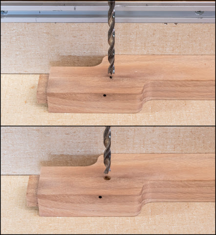
Drilling the pocket holes is next.  This is one time where I got my order of operations out of sequence.  I should have drilled the pocket holes in the guides before gluing them on but I didn’t.  It’s not a huge problem I just have to readjust the depth collar on the drill bit so the tip of it just comes through the piece.  This is how that adjustment looks like.

From here I can put the bit in the drill and bore the 8 holes for the screws.

After the holes were drilled, I was getting ready to fit the assembly in the cabinet and came across an unpleasant surprise.  The divider's notches are not identical as noted earlier and per the drawing below.  The front notches are deeper than the back ones and I had just drilled all the holes based on the shallower notch.   The result is the pocket holes in the front do not have enough material to provide for a strong connection.  This assembly provides support for the drawer and I am afraid that in use they would fail.  Needless to say, I was not very happy.  As near as I could tell two options were available.  First, was to remake the assemblies and second was to try and fix the problem.  If these were visible when the project is done a new set would be made.  However, they are inside the cabinet and not visible so trying to fix is an option. 

After some thought the only real option was to fill the holes and redrill the pocket holes.  The drill used to make the pocket holes is stepped with a large diameter of 3/8” so I needed a 3/8” oak dowel to fill the hole.  Taking a ½” square oak scrap piece from the project waste pile I turned a dowel to about a hundredth of an inch over 3/8”. 

Once the square ends are removed the dowel rough is cut to length and driven through the 3/8” die shown below that sizes the dowel to just what’s needed. 

The dowels are then cut to final length using the bench hook and Japanese pull saw like was done with the tenon patch in Post #6.  They are then glued and clamped in place.  The photo shows what they look like after the glue has cured and the clamps removed.

Cutting the plugs flush with the guides is next and the bandsaw is used to get close.  The left photo shows everything ready to go and the right photo shows the plugs cut off.

The block plane in the top photo below is used to bring the plugs next to it down very, very close to the guide’s surface.  The last little bit is taken off with a sander.  The top divider/guide in the same photo is done and ready to have the pocket holes drilled in the right place.  The bottom photo shows the same piece with the holes drilled.  All of this repair could have been avoided if I hadn’t gotten the order of operations out of sequence and drilled the holes before gluing the guides to the divider. 

Next Up – Drawer Divider/Guides Part 2 & Shelf Supports

Monday, August 23, 2021

Greene & Greene End Table - #14 Base Glue-up

Gluing all the pieces together is next.  Because there are a lot of joints and pieces that need to be carefully aligned there is no way to put everything together at once within the glue setup time limits.  Breaking it down into a few manageable stages will give me the time needed without rushing through. 

The first stage is to glue the back’s lower front rail, two spindles, two top rails and the veneered panels together.  The drawing below shows the pieces that will be glued together as follows:

  • With the veneered panels in place glue is applied to the top rails and spindle joints
  • The top of the spindle is adjusted to make sure it is flush with the top of the top rail.  A screw is then run in from the spindle into that rail pulling them tight together.  The same process is repeated for the other spindle.
  • Glue is applied inside the two spindle mortises in the bottom rail.
  • The spindle tenons in the spindle/rail/veneered panel assembly are then installed in the bottom rail mortises.
  • Both legs are put in place without glue and everything is clamped.  The assembly’s diagonals are measured to make sure the assembly is square.
  • A clamp is used to pull the spindle tight to the bottom rail then a screw is put in locking the spindle in place to the bottom rail and the clamp is removed.  The same is done with the other spindle.
  • Going back to the lower, upper rail a screw is run from the spindle into that rail pulling them tight together.
  • All the joints are check for glue squeeze out and cleaned as required.

The same process is followed for the front frame.  Here both are glued and clamped up curing.  Everything went smoothly, not rushed and with no problems.  

The next day the clamps are removed and the unglued legs are taken off.  The inside of the leg mortises get glue applied then they are put back on the already glued interior frame and the clamps are reinstalled.  When clamped the assemblies look the same as the photo above.  This completes the glue-up of the front and back assemblies.

Tying the front and back assemblies together to complete the base framework is next.  That’s done by gluing in the upper side rails along with the veneered panels and the bottom rails.  This drawing shows the pieces involved.

Before the gluing starts all the above listed pieces get dry assembled together with the front and back assemblies.  That looks like this.

Next is drilling some pilot holes for the screws that will lock the front assemblies and the sides together.  The drawing below is a section of the front left leg, side rail and top rail cut half way down through the tenon in the top rail.  The top rail had a countersunk pilot hole drilled through the tenon before the front/back assemblies were glued together.  What now needs to be located and drilled is the hole shown in the side rail’s tenon.  It was not marked before because I wanted the front/back glued up solid first.   There is a little gap between the end of the side rail’s tenon and the side of the top rail’s tenon.  That’s for a couple of reasons.  First, is in case a little glue gets built up when the top rail and the leg are glued together.  Second, is because I want the shoulder of the side rail’s tenon pulled up tight to the face of the leg.  If tenon is sized to the exact depth and I put too much glue in the joint, some debris get in there or any other obstruction then the rail can’t be pulled up tight to the leg.

This is what the assembly looks like in real life.  You can see the countersunk hole at the bottom of the mortise.  I used a pencil to mark the center of the countersink hole in the end of the sider rail tenon.  All 12 of the tenons that get screws get marked the same way.

After the holes are marked the base is taken apart so I can drill the holes.  In the top photo the piece to be drilled, which in this case is one of the top rails, is clamped in a vice and plumbed vertical.  You can see the pencil mark at the end of the tenon.  The drill has a 3/32” bit for the pilot hole of the #6 x 1 ½” screw and the piece of tape marks the hole depth.   Below the drill is the punch I use to make a starting dimple in the tenon.  Same process for all the holes.  The bottom photo is of the completed pilot hole.

Before reassembling the base, I checked the mortise where the tenons of the top rails had been glued into the legs.  The top photo shows a little gob of glue that I was concerned might cause a problem when I press fit the plug in place.  Only about half the tenons had this problem.  A couple of whacks with a wood chisel popped the glue right out.

You would think that I could do the final glue up but not quite yet.  There is one more step.  The whole base needs to be reassembled and the screws run into the just drilled pilot holes.  There is not a lot of wood around the screw that goes into the tenons and I wanted to make sure none of them were going to split while installing the screw.  For peace of mind, I did wax the screws to act as a lube.

Final assembly consists of spreading glue in the mortises then assembling and clamping all the pieces.  This glue up had 12 mortises and two veneered panels to fit together.  Once that hectic process had been completed the diagonals were check to see if the frame was square (it was).  Last is to put the screws back in.  Once glued up is looks the same as when I did the first dry assembly.

Next Up – Drawer Divider/Guides & Problem Part 1

Monday, August 16, 2021

Greene & Greene End Table - #13 Pre-Finishing, Stain Selection, Final Fit & Screw Pilot Holes

At last, all the oak base pieces are completed and are ready for a final test fitting prior to gluing up.  This is what they look like sanded ready for assembly and finishing.

During this assembly the veneer panels will be cut to size and any adjustment made to the grooves so everything fits together well.  This drawing shows where the veneer panels go.

Once all the veneer panels have been ripped to width and cut to length this is what the piece looks like from the back.  The front looks similar except the center panel will be a drawer faced with matching veneer. 

Looking ahead to how the finish is going to look I think that the veneer panels will just get sprayed with lacquer while the oak pieces will probably get a stain then sprayed with lacquer.  Even though the frame is not glued together it’s not too early to think through the finishing process.  The problem is in what order to do things so an early step does not cause a problem later on.  After some thought here are the steps, subject to change as I go along:

  1. Spray a scrap veneer piece with lacquer to verify it looks good without any stain.  If it doesn’t then do more testing on what stain may be needed.
  2. Using the completed veneer sample pick an oak stain, apply it to an oak scrap and lacquer.   If it doesn’t look right make adjustments to stain and repeat until it does.
  3. Finish the veneer panels with stain (if needed) and apply one coat of lacquer.
  4. Mask out areas of the oak frame that will get glued then stain.
  5. Final dry fit and drilling of various pilot holes for screws.
  6. Glue up frame.  Now this is going to be a whole different sequencing problem as there are a lot of joints that need to fit together just so and in the right order.

Here is what I use for spraying small projects with lacquer.  Since the sample pieces and veneer panels are all fairly small it’s what I’ll be using.  Starting at the back top left is the respirator mask whose cartridges are N100 filters plus they also remove both acid and organic vapors.   It’s setting on the gallon can of nitrocellulose lacquer.  On the right is a can of lacquer thinner used to thin the lacquer to proper consistency.  The next row on the left has two smaller bottles that go with the large HVLP sprayer.  Here I am using the left one for thinner and the right one for lacquer.  I use them as intermediates since I am less likely to make a mess when using them to load the small bottles on the right that get attached to the air-brush that applies the lacquer.  The left bottle gets filled with thinner and the right bottle gets partly filled with lacquer then thinned for application.  The lines on the right bottle let me track the ratio of the two.  On the far right are a pair of blue nitrile gloves for hand protection.  In the front on the left is a tack cloth used to remove any dust from the piece to be sprayed.  To its right is the sprayer and at the far right attached to the spray hose is the filter/regulator.  It removes any crud in the line from the air compressor and maintains the air pressure I have set on it feeding the air-brush.

Below on the top is the unfinished veneered sample while the one on the bottom has a coat of lacquer.  As you can see the lacquer makes quite a difference in the appearance.  The color is good but, in the photo, the light reflection subdued the grain effect.  It’s more pronounced in real life.

Taking the lacquered test piece, I sorted through my drawer of finish samples picking out the ones that seemed like they were possible candidates.  Below is the veneered panel surrounded by the samples.

Eliminating them one by one I ended up selecting Golden Oak.  Here is a scrap from the project with the stain applied and one coat of lacquer.

With the stain and finish decided on I can proceed with spraying the veneered pieces.  To stabilize them and help prevent any warping both sides get a coat of lacquer.  The top photo shows one coat of lacquer on the veneered face and the bottom side shows the back side with a coat.

While waiting for the lacquer to dry on the first side of the veneer panels I stained the oak pieces after putting tape on the areas that will get glued to keep them free of stain.

After letting the lacquer cure overnight, they are lightly wet sanded with an 1,800-grit pad.  This removes any dust or other flaws in the finish and flattens it in preparation for the next coat which will be applied after the table is assembled.

The back frame is then dry assembled, clamped and the diagonals checked.  If they are the same then the piece is square.  Fortunately, all the careful measuring and meticulous work paid off in that this assembly is dead on.  With that bit of good news, the locations for the screws can be marked.  One screw goes in each of the 14 mortises and along with the glue will lock the pieces together.  To keep from marring the stained surface the assembly is done on old towels.  Also, as shown in the bottom photo small wedges are placed between the leg and the clamp to prevent damage.  The wedges are cut from the tapered waste offcut so the angle exactly matches. 

Next is to drill the holes for the screws.  Typical of the process using the spindles (in top photo) as an example is to use a combination pilot hole and countersink bit in the drill press to drill the hole shown in the bottom photo.  Once the fence location and proper hole depth is set it’s easy to drill the hole in each of the spindles.  The rest of the holes follow a similar process that varies with the screw diameter and length.

I did have a problem with one of the holes.  The drill hit something in the wood probably one of the hard fall growth rings that deflected the bit a little causing the part to be pushed out of line resulting in an off-center hole.  I did notice it before the countersink was drilled so to correct clamped the part to the fence.  That held it in place when redrilling and mostly centered the hole allowing for an acceptable placement of the countersink.


Next Up – Base Glue-up

Monday, August 9, 2021

Greene & Greene End Table - #12 Routing Edges & Slotting Rails

With all the pieces cut and milled for the base I now need to go back and route a small 1/8” radius on most of the edges to soften them.  Of course, a little problem cropped up as I was ready to do the first piece.  One of the side rails had a couple of worm holes.  One of them is on the bottom of the rail and I can live with that but the other one is one the side.  When the table is done it will be on the inside but still visible and I suppose I could leave it but don’t want to.  The fix is to drill the hole out and patch it with a matching plug.  The top photo below shows a ¼” brad point drill in the drill press centered over the worm hole.  The bottom photo shows the drilled hole for the plug.


The plug is cut using a ¼” plug cutter mounted in the drill press.  The blank is from the waste cut away to make the offset just to the right of the worm hole.  Using that scrap should give me a plug that matches the color and grain really close.

Once cut the plug is popped out of the blank and glued in the rail.  The top photo shows the plug blank minus the plug and it glued in place.  One thing to note is the direction of the gain.  The plug’s grain needs to run parallel to grain in the rail otherwise it won’t blend in.  Voice of experience there.  The plug is cut just proud of the rail using a pull saw whose teeth have no set.  The blue tape gives me a visual if I start to cut a little deep.  The bottom photo shows the plug cut off.

Here is what the rail looks like with the completed plug sanded smooth with the rail’s surface along with the pull saw used to cut the plug off flush.

With that detour done I can work on the routing.  Below is the bit set in the router table so the bottom corner of the bit’s arc is flush with the table.  On the rail the top right edge has been routed while the three others still need to be done.  Since all the table base parts have most of their edges routed there are a lot of edges to do.

The legs have a quirk on one edge.  Three of the edges get a full-length routed edge.  However, the inside corner only gets routed up to the bottom of the lower rail.  The stopping point is circled in red.

The stopping point is eyeballed short at the router table and a pencil line is marked on the fence.  The edge is routed to see how much it is actually short then a new line is made and the edge routed again.  A couple of tries gets it close.  Once that’s done and the side rail is set in place some hand work is needed to make a smooth transition as illustrated in the top photo.  That’s done with a small fine-toothed file then the leg is finish sanded to 220 grit sandpaper and any touchup work at the intersection is done.  The file and finished intersection are shown in the bottom photo.

Most of the edge routing is pretty straightforward I just need to be careful to note which edges are routed and which are not.  Routing the front/back rails requires a two-step process because of the notch in its top.  First is to set the edge of the bearing flush with the router table fence.  Without the fence the bearing would drop into the notch and round over the notch’s edges which need to be kept square. 

To route the rest of the rail the fence is moved out of the way to provide access to the bottom of the notches and the tapered ends.

The last bit of work on the base involves making provisions for attaching the side rails to the wood top, that is if I go with a wood top instead of a stone top.  Attaching a wood top is not as simple as either gluing it down or running some screws up from inside through the rails into the top.  That’s because of the way wood moves when exposed to different humidity levels.  A solid oak top expands or contracts across the grain in response to the humidity change as do the rails while the change along a piece’s length is negligible.  The problem is the rails are 90 degrees to the top.  That means the top wants to expand and contract while the rails don’t.  If the top is solidly attached to the rails the forces can be enough to split the top when it moves and that’s not a good plan.  To get around this a single screw is run through the center of the side rail into the top to keep it in place.  Then to allow for the top to expand and contract about its center line the end holes in the side rail are really slots with the screws just pulled down snug.  This leaves the top free to expand or contract and not split as the humidity changes.  Once the slots are laid out the center point is marked with a punch, a hole is drilled at each end and one between them.  Here in the top photo, you can see the layout punch marks for the alignment hole in the center along with the slots at either end.  The tool at the bottom of the top photo is my spring-loaded punch.  The lower photo is a close-up and you can easily see the centering punch marks.

After the holes are drilled the interior edges of the slots are cleaned up using a Dremel tool with a spiral cutter then finished with flat and round rifflers.  This is what the slots and the center hole look like completed.

Here is what a set of rifflers look like.  If you are interested, this link will take you to the project, I did to make their handles and build their storage case.

 Next Up – Pre-Finishing, Stain Selection, Final Fit & Screw Pilot Holes