Router Plane

Thursday, August 27, 2015

Open Segmented Bowl – Material Selection, Preparation and Setup

Before I get into the segmented bowl discussion I have had a couple of people ask about what I ended up doing for the low voltage drive lighting.  So, I thought I would take just a little space and explain.  Where we live there are no street lights and if there is no moon it is very dark.  When we moved in the first few nights were moonless and coming back after dark we drove right by the house turned around, and then drove right by it going the other way.  The house sets back far enough and the plants are tall enough it’s really hard to see.  The only glow is from the lights in El Paso, about 40 miles away.  A couple of solar lights temporarily marked the driveway but they had started to fail so some replacements were needed.  As I talked in the first blog I went down the route of wired low voltage fixtures but due to costs opted for high quality solar powered lights.  The end installation is the photos below, taken at dusk.

Entry Drive Low Voltage Lighting

Low Voltage Lighting, Front Entry

Back to the segmented bowl.  My next decision was on which wood to make the piece out of.   Because of the small scale of the piece I wanted to use a fine grain wood.  Based on what I had in stock my choices were Maple, Walnut, Cherry, Poplar, Zebrawood, Katalox, Mesquite, Cocobolo, Ebony, Lacewood and Padauk.  I also wanted something that would not overpower the simple design so that eliminated Zebrawood and Lacewood.  Narrowing it down to what I had in the scrap box gave me Maple, Cherry, Walnut and Poplar.  The Maple, Walnut and Poplar were all nice flat rectangular boards ready to be go.  The Cherry on the other hand was leftovers from the Maloof rocking chair.   In cutting out all the curved pieces for that project I ended up with a lot of strange shaped mostly 1¾” thick fairly short pieces so trying to use them for this piece seemed like a good use of cutoffs, besides I like to work with Cherry.
Scrap Cherry Pieces


As these leftover pieces had been cut to make curved blanks for the chair I had no straight edge to work from or the grain ran at a strange angle to the edge.  The good news was that they had already been prepped for the chair so the top and bottom faces were flat and parallel.  For each of the pieces I started by drawing a straight reference line using a steel straightedge and cutting to the line as straight as I could with the bandsaw.  
Cherry Scrap - Bandsawn Edge

With a reasonably straight edge to start with I cut the opposite edge true on the table saw.
Cherry Scrap - Finished Edge at Back
I then flipped the piece over and set the just sawn finish edge against the table saw fence to clean up and true the bandsawn edge.  This only works with a good bandsawn edge and pieces that are short enough to be fully registered against the table saw fence both before and after the cut.  I am not advocating this method for all but it works for me.  For longer pieces I would use a plane to clean up the bandsawn edge and then use that against the table saw fence.  A joiner would be great but I don't have one, but then most of these pieces are a little short to run through a joiner.
Cherry Scrap - Sawn Bandsawn Edge
Now that I had rectangular pieces to work with I set the table saw up to cut blanks at slightly over my finished size of ½”. 
Table Saw Setup for Ripping

I cut the blanks slightly oversize because I will use the thickness sander to remove the inevitable burn marks or irregularities and take them all to the same thickness.  I can also get the blanks to a nearly finished state using 220 grit sandpaper in the sander.  
Thickness Sander & Cherry Blanks

Here are the blanks all the same thickness but random lengths and widths ready to go.
Finished Cherry Blanks

My plan is to make the bowl in two pieces, a top half and a bottom half then glue them together.  To start I cut a ¾” thick cherry base in a rough circle slightly larger than needed on the bandsaw.  I then glued it to a sacrificial base made out of a piece of 2x4 I had screwed to a face plate and turned it to a true circle.  The easy way to glue and center the cherry is to use the tail stock on the lathe to provide the clamping pressure.
Bowl Bottom  Glue-up

I have only one regular faceplate so for the top half I used a scroll chuck to hold the sacrificial piece. This one is made from two layers of particle board and a layer of thin plywood.   This piece is from a scrap off the jig I used to laminate the rockers for the Maloof chair.  Like the bottom setup I took the cherry top I had bandsawn to a rough circle then glued it to the sacrificial base.
Bowl Top Glue-up
With both the top and bottom solid pieces done I was ready to get started on cutting the segments.  I began with the bottom half, the layer up from the solid bottom is layer 1.  Checking my cut list the blank Width for layer 1 is 1.941” (highlighted in yellow).  I set the table saw up and ripped a couple of pieces that width.  I am not concerned if I overshoot the number of pieces I need as there are several layers that are narrower and I can always recut the blanks.

Next is to set the table saw jig up for the Outer Face Length for layer 1.  Going back to my cut list shows it’s 1.009” (highlighted in yellow). 

Using my digital calipers I set the right hand stop on the jig for 1.009" and cut a test piece.  
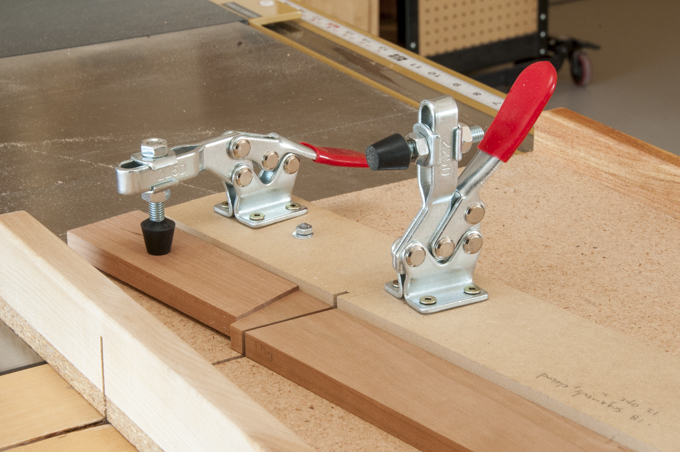
Table Saw Jig Setup

With it measuring out right I cut 13 pieces.  The 12 needed plus one in case of a problem.

Next up – Gluing the Segments

Thursday, August 20, 2015

Open Segmented Bowl – The Jigs Part II

The final jig runs in the left miter slot on the table saw and is used to cut the pieces a specific length at the required 10° angle. 

Table Saw & Jig
With one exception it’s pretty straightforward to build.  I started with a piece of hardwood cut to fit snugly in the miter slot in the table saw and screwed it to a particle board base.  One problem I did run into was that I was having a hard time making the runner run smoothly along the entire length of the miter slot.  The runner would have a good fit and then jam depending on where it was in the miter slot.  Some close examination and measuring revealed the miter slot was not a consistent width from end to end.  There were also little scallops of varying size remaining all along the slot from when it was machined. 
 
Scallops in Table Saw Miter Slot
The fix was to take a 10” metal file hold it flat against the sides of the miter slot and carefully file the face getting rid of the high spots. 
 
Filing Edge of Miter Slot
It took less than 10 minutes and made all the difference.   I just had to hold the file square and keep an even pressure on it from one end of the slot to the other.
 
Filed Miter Slot
With the runner mounted to the base I marked the saw blade path through the jig, mounted front and rear braces keeping the screws away from the blade path.   Hitting a screw with my good cutoff blade would be an expensive mistake and make me say bad words.  I then made the initial cut in the jig going only far enough into the jig so as to be able to cut the segments.  The last piece to be mounted to the jig is the fence.  This is the most critical part and the one that you can count on taking some time to get just right.  Process is to mark the 10 degree angle off of square to the saw blade, align the fence to the line and on the right side screw the fence to the base with one screw.  That screw that will act as a pivot and allow for the fine tuning to come.  Next, swing the left side of the fence down so the angle is just slightly more than the 10° and on the left side of the fence screw a stop block to the base below the fence.  The photo below will help make this all clear. 


The fence will still rotate because it’s only fastened at one end.  This is planned so that the needed fine adjustments can be made.  Next, clamp the fence to the block to hold it in place for our test cuts.


Prior to making the test cuts I added a couple of toggle clamps.  The one on the outside sets the segment Outer Face Length and the other clamps the blank in place when it gets short.  The second clamp also acts as a guard to help keep my fingers out of the blade path. 
 
Both Toggle Clamps Installed
Before setting up the jig I ripped a scrap piece of plywood 1½” wide for my test blank.  The right toggle clamp is then used to set the stop block for the Outer Face Length at about 1¼”.  I did add a thin spacer under the stop block to help keep sawdust from getting trapped and impacting the accuracy.  Cutting process is to first trim the end of the blank to get one angle. 
 
End of Blank Trimmed to 10 Degree Angle
Second, flip the blank over and cut the first segment. 
 
First Test Segment Cut
Third, is to flip the blank over and cut the second segment.  The process is repeated until you have cut 18 pieces to be put together for a test fit.  
 
Second Segment Cut
Why 18 pieces and not 12 since I am making a bowl with 12 segments per layer?  It’s because the bowl is an open segmented piece.  Remember for an open segmented piece each solid segment covers 20 degrees plus the 10 degree gap equals a total arc covered of 30 degrees.   So, 12 pieces times 30 degrees each equals the 360 degrees in a circle.  However, for our accuracy test we need to make a solid ring.  With each piece cut at 20 degrees I need 18 pieces to equal 360 degrees.  Making the test fit requires clamping up the 18 pieces in a ring.  For me using a hose clamp works the best.  
 
First Set of Segments Test Fitted
Getting a perfect fit requires some trial and error since there are so many cuts.  Just think, for the above ring there are 18 pieces with two angled cuts.  This means that whatever error you have per cut gets multiplied by 36.  This is why a tiny error in each cut becomes a real problem.  Because I set the stop block so the fence was just a bit more than 10 degrees I can sneak up on the correct angle by adding thin shims between the stop block and the fence.  Playing cards to start with and masking tape at the end.  It is an iterative process of cutting pieces, assembling for a test fit and adjusting the fence as needed.  When the ring fits together with no gaps the fence is securely screwed to the base.  The good thing is that you only have to do this once.  When the jig is adjusted perfectly the pieces go together in a circle and there are no gaps at any of the joints like this ring. 
 
Final Test Ring - No Gaps!

Next up – Material Selection, Preparation and Setup

Thursday, August 13, 2015

Open Segmented Bowl – The Jigs Part I

Now that I had the design and a cut list I needed to build four different jigs to cut and assemble the pieces.  Rather than show a completed picture and say, “I built the jigs.” then let it go from there I had planned on spending a little time going through the jig building process.  The jigs are important since if they are not right the piece won’t be either.  However, as you can see this post is titled The Jigs Part I which means there will be a Part II.  As I developed the jigs the build process got a bit more complicated than I thought and the information grew.  It finally got to a point where I needed to break the material into two posts.  So this post covers the jigs that get mounted to the lathe.

The process starts by making some drawings to get the design down and figure out what I need in the way of materials.  Three of the jigs get mounted on the lathe. 
Drawing of Jigs for Lathe

The first and easiest is an indexing wheel.  It along with the second jig is used to accurately set the individual segments every 30 degrees and to offset the adjacent layer by 15 degrees.  I printed out a paper copy of an indexing wheel made for a 12 segment design, glued it to a piece of thin plywood cut it out on the bandsaw and sanded the edges smooth.  
Index Wheel Drawing and Paper Glued to Plywood & Cut Out
The jig is mounted on the rotating part of the lathe.  Its location is shown in the left photo by the red line on the spindle shoulder.  In my case all I needed to do was drill a hole the same diameter as the spindle shoulder and set it in place, middle photo.  When I thread the face place onto the spindle it will act as a clamp and hold the jig firmly in place, right photo.
The second jig is used to align the guide lines on the index wheel to a specific point and as an extension of that the bowl blank mounted to the lathe.  When clamped to the index wheel it holds the bowl blank in a fixed location so the segments can be located and glued in place.

Alignment Guide Jig Parts
There are just a few pieces in this jig:
1.  The alignment guide made out of clear plastic.
2.    A plywood backer to support plastic.
3.    The top crosspiece that goes across the lathe ways to which the alignment guide and its backer are screwed to.
4.    A spacer that goes between the ways to keep the jig square to the spindle axis and hold it a fixed distance away from the lathe headstock.
5.    A clamping bolt that when tightened holds the jig in place.
6.    The bottom crosspiece which goes below the ways that the clamping bolt is threaded into.

Only a couple of pieces need to be cut and located carefully.  The top of the alignment guide needs to be right at the centerline of the spindle.  You want the line on the index wheel to be parallel with the top of the alignment guide.  If the alignment guide top is above or below center then it will never be in correct registration.
Alignment Jig & Index Wheel in place


The other piece is the spacer that goes between the lathe ways.  To keep the jig square it needs to be moveable but not a sloppy fit.  I spaced mine the thickness of a playing card (about .01”) less than the ways spacing.  The piece in the photo is long enough for both this jig and the next one. 
Alignment Jig and Gluing Jig Spacer

Its length needs to be cut so when it butts against the headstock it holds the plastic alignment guide about 1/16” out from the index wheel.  Lastly, the spacer and top crosspiece are fastened together at 90 degrees.

To make the clamping bolt knob here is the process I go through.  I start with a template to layout the shape, bandsaw it close, finish shaping on the disk sander, cut a square mortise for the carriage bolt lugs, drill a hole for the threaded shaft of the bolt, round the edges, sand smooth and finish.

The clamping bolt goes from the top crosspiece through the spacer then on through the bottom crosspiece and typically into a nut.  To me that’s just one more piece to lose or fumble around trying to get my hand between the ways without dropping the nut so I can get it started on the clamping bolt.  For me an easier way is to use a metal threaded insert set in the bottom crosspiece.  Here is what it looks like installed.


The inserts often come with a slot that would lead one to believe they can be easily installed using a screw driver.  To that all I can say is, “Fat Chance!” I tried and it was a disaster.  I have had good luck with this method:
1.    Threading an insert on a threaded rod and holding it in place with a jamb nut
2.   Mounting that assembly in a drill press
3.    Use the spindle feed handles to start the insert and put some pressure on it.
4.    Turn the drill press chuck by hand to run the insert in to the desired depth. 

One thing, just don’t turn the drill press on to run the insert in.  If you do it will be thrilling but not the kind of thrill you really want.

The last jig that gets mounted to the lathe is the Gluing Jig.  It makes sure the segment is set parallel to the layer center line and that it is at the correct distance from the layer center point.  While the actual size of the jig is not critical I made it large enough to be rigid when clamped in place.  My base ended up being 12 ½” x 14”.  As with the last jig there are a few things that are important such as keeping the pieces square and plumb with the lathe ways. 

Gluing Jig

However, the location of the aluminum angle at the top is the one item to really pay attention to.  The top corner and its horizontal cut edge needs to be right on the centerline of the spindle because that is your reference point for setting the outside edge of the segment.  If it is off then so will your layer diameter which impacts the gap size and the size of that little glue joint which holds everything together.  The long part of the angle needs to line up with the center line across the face plate.  If it’s out of parallel with the ways, too high or too low then the segments will be twisted when you look down on the ring. 
Aluminum Angle Aligned to Centerlines
This completes the jigs necessary to accurately locate and glue the individual segments in place.
Completed Jigs Ready to Use

Next up – The Jigs Part II


Friday, August 7, 2015

Open Segmented Bowl - The Start

At the end of the Maloof Chair blog I had talked about another project I had in mind.  I did not mention what, but it was some low voltage exterior lighting fixtures.  I finished up the design, built a mockup and  was ready to go.  However, because of escalating project costs I reviewed my cost estimate to make sure I had everything and found I had left out one item, the nearly $200 of wire needed to connect all the lights together.  That pushed the project out of what we had budgeted.  At that point it was back to the drawing board where we found some quite nice solar LED lights.  They have a soft yellow color and provide enough light to meet my goal of highlighting the limits of the driveway for less than 20% of my final estimated cost.  Also, the idea of digging several hundred feet of trench by hand was not all the appealing.

This all led to the next project on my bucket list, a segmented bowl turned on the lathe made with gaps between the segments.  I have done several solid segmented wood turning pieces and  wanted to see if I could do one of these. 

 
I started out using SketchUp to make a general profile drawing of what I wanted the bowl to look like.  The next step is to take that profile turn it into a 3D rendering  and take a critical look at it.  It’s then back to the profile to edit as needed, create a 3D rendering, evaluate that and repeat the process until I get the final shape.  “Final” shape is a rough term as things can and often do change as I go through the building process.  With the aforementioned “final” shape done I made the decision that there would be a one piece top and bottom with 6 individual segmented layers between.  The top and bottom layers would be 3/8” thick and the segmented layers would be a ½” thick.

Before I go into the specifics of the math needed to size the individual segments here is the finished drawing of the piece.  I include it here to help out with the visualization of the following series of decisions I made .


My next step is to decide how many segments per layer.  I want the segments to be big enough to work with but not so few as to make the piece look clunky.  To get the outer face sizes meant I needed to create an Excel spreadsheet to run the geometry calculations.   I made one assumption in the calculations, and bear with me as I go through the logic.  Each piece in the open segment layer would be 2/3 the angle of a piece needed for a solid layer leaving a gap between segments equal to 1/3 the angle of a solid piece.  Got that?  To help here is an example, if there are 12 pieces in a solid ring each piece covers 30° (360° in a circle divided by 12 pieces).  This means each of the 12 pieces in the open segment piece would cover 2/3 of 30° or 20° and the gap between the segments would be 10 °.  The drawings below should help out, a solid ring on the left and the open segmented ring on the right.


I chose a 10° gap as a balance between openness and strength.  The bigger the gap the more delicate and airy the piece is but the less glue surface there is holding it all together.  Remember, when I get the ring layers all glued together I am going to mount it in the lathe and spin it at well over a thousand revolutions per minute.  Once at speed I will then shape it freehand using a lath chisel.  The piece needs to have enough strength to hold together and not fly apart due to centrifugal force or from the impact shock when that steel chisel starts cutting away.  After all, that little 5° glued overlap between pieces is all that is holding everything together and if it lets go pieces will fly!  Exciting, yes but not the kind of excitement I am after.

With that one assumption I built a spreadsheet to give me the outer face segment length for each layer based on two entries, the number of segments in the layer and the layer radius .  The radius for each layer comes from the final profile drawing  as does the segment width by layer which I will use later.

In reviewing the calculations it looked like a 12 segment ring would make the smallest piece just under an inch wide, which for this piece is a good size to work with.  Also, since the pieces are tapered this is the largest dimension, the inside face will be smaller.  With the number of segments set I had the calculated outer face length and from the drawing I got the segment width by layer.  Plugging the segment width by layer into the spreadsheet gives me the inner face length.  Using all the data gives me the needed board length for each layer  required to cut the segments.  With this I had everything needed to generate my cut sheet that showed everything I needed to build the piece.


It was using this data I created the final drawing shown above and here below.  Note the Material column is blank.  I have not yet decided what wood to make it out of although the stack of leftover scraps from the Maloof chair do come to mind....  While the drawing gives a good idea of the overall shape it does not show all the corners cleaned up and smoothed together.  However, it’s good enough to proceed on with the project.


Next up – The Jigs