Router Plane

Monday, February 26, 2024

Wastebasket – #4 Attaching Side Braces, Spacer Base & Moving Index Assembly

Attaching the Side Braces pieces are next but before they can be installed one of them needs to have a hole drilled for the locking bolt and a threaded T-nut for the bolt to run through that will clamp the spacers in place.   The top drawing shows the hole for the bolt and the bottom drawing shows the T-Nut installed in a recessed hole so it ends up flush with the face of the Side Brace.  To make the recess for the T-nut I used a flat bottom Fostner bit then drilled the through hole with a regular twist bit.

To install the Side Braces, one gets clamped in place and five screws are installed, three from the bottom and two from the Fixed Backer using the same pilot and countersink hole method as before.

The Spacer Base gets set in place next which is shown in the top drawing.  It’s a 25+ year-old piece of 2x4 that was salvaged when I remodeled our Master Bath.   A couple years ago some of those salvaged pieces were flattened then made square and true for another project.  This off cut is one that just needed a little trimming to width and thickness then cut to length.  With it in place the second Side Brace is set where it goes.  Next is to add the silver end to end clamp.  It pulls the Side Braces and the Spacer Base tight together.  Additional clamps are added to hold the second Side Brace in place while the screws are put in just like the first one.

Last is to run several screws up through the Base into the Spacer Base to lock it into place along with a single screw through each of the Side Braces into the Spacer Base lock those pieces together.

As the project has progressed, I have been checking all along to make sure everything was square which it was.  However, when checking at this point there was an unpleasant surprise.  The Base and Fixed Backer were no longer square (insert the many bad words said here).  It’s not out of square a lot maybe 3/32” over the height of the Fixed Backer but it’s enough to make be worry that the cuts for the box joints would not be square.  With everything glued and screwed together there is not really any good way to square the two pieces without starting over.  After some thought I decided to add a thin shim at the top of the Fixed Backer which will then bring the Moving Backer back into square.  This is the part the box joint blanks will get clamped to and be registered for squareness against.  The top photo shows the shim installed while the bottom photo is a closer look at one end.

Attaching the Moving Backer to the Moving Index Brace is next.  Those two pieces are shown in the inset drawing below.  In use the Moving Index Brace will set on the Fixed Backer then slid back and forth to make the box joints.  So the Moving Backer won’t rub on the Base my 24” steel scale is used as a spacer to raise the Moving Backer up off the base.  A close view of that is in the top photo while the bottom photo shows how it looks with all the screws installed.

After adding the shim to square up the jig I now need to angle the top of Fixed Backer (red arrow) so it’s square with the Base.  That’s done using a block plane.  To help give a consistent angle there are three layers of masking tape right at the edge of the plane to give the proper angle.

Another piece whose edge has to be cut at an angle is the Moving Indexer shown in the drawing.  When measured the angle comes out to 1.2 degrees.  Once the table saw is set using the digital gauge it’s easy to cut the piece to fit.

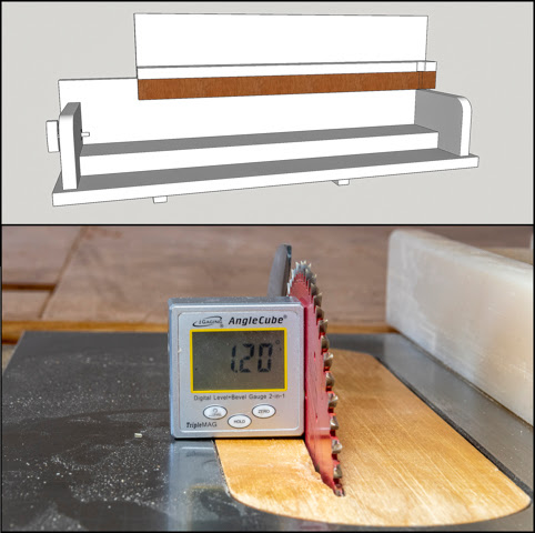
Installing the Moving Indexer is next and to set the gap so the finished assembly moves easily but without much play three layers of masking tape get used as a temporary spacer per the top photo.  The bottom photo shows it in place with the five screws installed but before the clamps are removed.  Once the masking tape is removed the whole assembly moves freely without being loose.

To control the fit of the box joint a Moving Indexer and Index Guide is required.  The original plan had a wood spacer for the Index Guide that matched the thickness of my 1/8” wide rip saw blade.  During the build I decided to change the blade to a ¼” stack dado set with a .004” spacer.  I will explain the reasoning behind the .004” spacer later.  The reason for the change to the dado set is that it will give me a flatter bottom of cut and I will need to  make only half as many passes through the saw to cut the box joints.  The top drawing shows the two options considered while the bottom photo shows the selected layout and bolt that will be used for the Index Guide.

Milling the place where the bolt goes is a three-step process.  It’s all done using the drill press with the Moving Indexer clamped in place.  First, is using a ¾” Fostner bit a half hole is drilled through the Moving Indexer Brace and into the Moving Indexer.  The setup is shown in the left photo.  In the middle photo that hole has been drilled and a ¼” bit has drilled the hole where the threaded part of the bolt will go.  Last in the right photo a 5/16”-18 tap is used to cut threads in the wood matching the threads on the bolt.

With all of the drilling in the Moving Indexer done I can put temporarily install my Index Guide (bolt) through it.  Here is a better view of the finished Moving Indexer along the bolt, washers and nut to lock it into place.  While the hole in the Moving Indexer has threads that match the bolt the fact that they are cut into plywood makes them not very strong.  My plan is to use the threads to register the bolt in place then use the steel nut and lock washer to hold it there.  However, before the bolt can be installed the end of it needs to be sized which I will do in the next post.

Next Up – Index Guide & Jig Testing

Monday, February 19, 2024

Wastebasket – #3 Fixed Backer, Sides & Table Saw Guides

As I was checking the dado, I noticed a couple of places that the dado blade had not cut to its full depth.  Probably because I was not holding the piece tight enough to the table saw’s top.  I could have reset the fence and recut that part of the dado again but decided to use a hand router I made in 2020.  It’s easy to use for the small bit of touchup needed.  Just set the blade in the router to the desired depth then gently run it along the dado using the two knobs for control.

Because the Fixed Back is sized to just fit the dado a small hand plane is used to make a small bevel on the long edges that fit in it.  The top photo shows the Fixed Back in the vise and the hand plane used.  Bottom photo is a closeup of the bevel.

Here you can see how the two pieces fit nice and tight together.

Drilling the holes for attaching the Fixed Back to the Base with screws is next.  With the two pieces still together the hole locations are laid out on the bottom face of the Base.  First, using the thin drill bit (on the left) drill a hole the same depth as the screw on the right’s length.  Second, is to disassemble the pieces then use the countersink (center) to taper the top part of the hole so the screw head will be just below the Base’s surface.  Last is to use the right drill to make a clearance hole just big enough so the threads on the screw do not bite into the Base.  Since the screws are used to pull the Base tight to the Fixed Back the Base needs to be able to move up and down the screw.

Before assembling the Base and the Fixed Back the Side Braces get made so I can clamp them in place to help square the Fixed Back to the Base.  There are two, one at each end of the jig shown in the top photo.  They are cut from a small piece of ¾” thick oak veneered plywood on the table saw.  So, I don’t whack myself when using the jig, the exposed corner gets rounded.  After laying out the curve the bandsaw is used to rough cut the curve.

Smoothing the bandsawn edge is done with the large disk sander.  The bottom photo shows the smoothed finished edge (except for hand sanding) on the left and the bandsawn edge on the right.

Gluing and screwing the Base and Fixed Back together is next followed by clamping the Side Braces in place.

After checking to see if the Saw Slot Runners still run true in the saw’s miter slots they get a tiny rabbit cut on either top edge.  The inset is a closer look at the router bit and notch.  This should give any glue squeeze out that happens when they are glued in place a space to ooze into so the jig does not get glued to the table saw’s top.  It will also make any minor adjustments needed after they are glued in place easier to do.  The red arrow points to the notch cut by the router.  Just to its right is the second Runner flipped over so the rabbits are easier to see. 

Gluing the runners to the Base is next.  The top photo is the first step where a thin shim has been set in the miter slot.  It’s thick enough so the top of the runner is about 1/16” proud of the saw’s top and the fence is set to act as a reference to make the Base square with the saw blade.  The bottom photo shows the runners in place ready to have a thin bead of glue applied so as to minimize squeeze out.

Next shown in the top photo is after the Base assembly has been set in place on the runners, butted up tight to the fence so it’s square with the saw blade and two clamps placed to apply pressure to the glue joints.  The bottom photo is of the back side where two more clamps are used to apply pressure to that side of the jig.  After letting the glue cure overnight, the clamps come off and the assembly tested to see if it runs smoothly and if not, the runners are adjusted as needed.  Over the years I have made several jigs that use runners like this and they have always needed a certain about of adjustment to get a smooth fit.  This is the first time where they fit perfectly the first time.  It is also the first time I have used the saw’s fence to square the assembly and the first-time using clamps to hold everything in place while the glue cures.

While the glue would probably hold the runners solidly in place I added a few screws for some mechanical fastening, just in case.  The screws used are not flat head but round head as shown in the top photo.  Flat head screws are not used because their tapered underside would act like a wedge causing the runner to widen slightly binding the runner in the saw’s miter slot.  The inset shows just the head of the round screw with its flat underside so you can see what I mean.  The drill on the left is a Brad point type that makes a flat bottom hole which matches the underside of the screw head.  The next bit over is used to drill a clearance hole though the runner for the screw itself.  Tape is used to as a guide to mark the hole depth.  The bottom photo shows the runners with all the mounting holes drilled and a couple of the screws installed.

Next Up – Attaching Side Braces, Spacer Base & Moving Index Assembly

Monday, February 12, 2024

Wastebasket – #2 Jig: Materials, Runners & Part 1 Base

The jig for cutting the box joints sets on the table saw as shown in the photos below.  The top is from the user’s standpoint behind the saw and the bottom photo is from the front that shows the two different pieces of the wastebasket.

Picking material is next.  Baltic Birch would have been my first choice but it is no longer available in the area where I live.  Because the quality of regular plywood is not consistent enough for this project, I decided to go through by stack of leftover furniture grade veneered plywood and came up with these pieces of oak and mahogany.  There is also one piece of vinyl skinned MDF.  It may be used for the sliding part of the jig to reduce friction and because screwing into or gluing of the piece is not required.   There is also a small scrap of quarter sawn red oak that is for the runners.

The runners will sit in the two miter slots in the top of the table saw and will guide the jig while it’s being used.  The red arrows in the top drawing point toward the two runners.  The fit of the runners in the miter slot is critical to the overall performance of the jig.  They need to just fit in the slot with no noticeable play but without binding.  There is not much tolerance in the fit.  Quarter sawn red oak was chosen for its stability and because it’s a hardwood.  The blank started out at about .775” and the miter slot is a nominally ¾”.  Since the oak blank is only about .025” oversize the thickness sander is used to gradually thin the blank down to fit.  In a perfect world the table saw slots would be exactly ¾” with perfectly parallel sides.  Unfortunately, that’s not the case.  As I got close the blank would fit in some places and bind in others.  In the past when fitting the steel guide on the saws miter fence I ran into the same problem and ended up using a file to smooth out the sides of the slot as there were scallops from the original milling of the slots.  Apparently, the work I did while enough to make the fence run smooth it wasn’t enough for these runners.  After locating the high spots and about 15 minutes of work with the file the oak blank ran smooth without any play.  However, the slots are not the same size as one is .753” wide while the other is .757”.  Not a lot, but enough that the narrow runner would show obvious play when put in the other slot.   Anyway, the bottom photo shows the oak blank fitted to the wider slot.

The slot is a little over 3/8” deep and the blank needs to be a little less than that for clearance.  Here is the saw setup for ripping the runners.  After the second runner is ripped it gets thinned down to fit in the narrower slot.  Also shown is the yellow safety push block I use to keep my fingers away from the blade. 

With both pieces fitted to the slots width they run through the thickness sander is used to remove any saw marks and get to the desired clearance.  Here the gap shows the difference between the runner thickness and the depth of the slot in the table saw.  With that done they are set aside to make sure they don’t warp, twist or otherwise move around.

Next is to take the mahogany veneered piece of plywood and start work on the jig’s base which is shown in the top drawing.  Before that I need to change the blade on the table saw.  The blade now on the saw is for ripping or crosscutting solid lumber not plywood.  If it’s used to cut plywood the cut edge is terrible, rough with the finish veneer all chipped along the cut.  The bottom photo has the current blade on the left and the plywood blade on the right.  Besides the difference in tooth count the geometry of the grind of the carbide tips between the two is drastically different.

First is to get a straight edge to work from since the existing piece’s edge was cut freehand.  You can see the gaps under the level in the top photo.  To get it ready to straighten I had to knock the high point down in the center using my hand plane so the panel would not rock when it was set up against the 8’ level and run through the table saw.  Once the first edge is straight the piece gets flipped and that straight edge used to cut the original edge true.  The completed cut is shown in the bottom photo.

Cutting a clean square edge is done with my sled on the table saw.  Here the first edge is trued up which is followed up by flipping the piece and cutting the other end giving me a blank with straight parallel edges and 90-degree corners.

The short edges get checked and the worst one gets cut off when the panel is cut to length.  Last is to cut the base to width and then use the offcut to make the Fixed Back.

Cutting the dado in the base where the Fixed Backer will go comes next.  This starts by swapping out the plywood cutting blade with my stacked dado.  The reason for this change is because I want the bottom of the cut to be flat.  Here the cut on the left was made with the dado blade while the cut on the right is what the plywood blade makes.

In the top photo you can see the two 1/8” wide dado blades I used to make roughly a third of the cut.  If I wanted to make a wider cut with each pass I would have added chippers between these two.  The bottom photo shows the base where the white piece on the right is the table saw fence.  The dado gets made in multiple passes starting at the right then the fence gets moved to the right which makes the dado blades cut the dado wider on the left side until the dado just fits the Fixed Backer.

Next Up – Fixed Backer, Sides & Table Saw Guides

Monday, February 5, 2024

Wastebasket – #1 The Start, Design & Material Selection

Not too long ago the small plastic wastebasket in the second bedroom where we have the desktop computer and its related peripherals just fell apart due to old age.  As a temporary receptacle we stuck an old kitchen garbage can in there.  My wife suggested we go somewhere like Walmart or Home Depot to get one similar to the old one.  Now that’s probably the quickest and easiest solution but I had another idea.  Why not make a nicely designed one out of cherry to match the desk and side unit since there is fully dried cherry in my wood stack just waiting to be used? 

First step is to sit down and do some sketching out of different designs then take the promising ones and draw them up to scale in Sketchup refining the proportions and making sure a small wastebasket liner will fit.  In the end I came up with five different designs. 

The far left one is pretty straight forward but has some problems with accommodating the cross-grain expansion or seeing end grain and I don’t like either.  The next one looks simple but the tapered corner miters are anything but.  They require both a tilt to the blade plus an angle set on the miter gauge.  Also, once assembled the corners will need to be reinforced with splines for strength.  The math for calculating the angles gets a little messy but if you are interested here are the formulas:

Miter Angle= Inverse Tangent (1 /(Cosine in degrees * Tangent (360 degrees / 2 * number of staves)))

Blade Angle= inverse tangent (cosine of MA* Tangent of Slope angle)

Grinding through the calculations gives a Miter angle of 85.012 degrees and a Blade angle of 44.78 degrees.  The center one is a segmented turning that would provide the opportunity to add some interest in the layers but I recently completed a segmented piece so want to try something different.  The right two are similar where one has dovetailed corners and the other uses box joints. 

After some thought I decided to develop the far-right sketch that uses box joints at the corners because I like the effect the box joints give.  However, rather than use equal sized box joints I decided to see what using two different sized joints looked like.  The drawing below shows the result when alternating between ½” and 1” box joints.  The colors are only for making the joints easily visible.

With the dimensions of the piece known it’s off to the lumber stacks to pull material.  Below are four cherry boards that are possibilities.  I will only be using two but haven’t decided which two yet.

Because angled box joints are nothing I have ever tried before there will be some testing to make sure that I can make what I designed.  As an architect friend once said, “Every designer should have to build what they designed.” a quote that has come back to haunt me time and time again.  My test material is 5/8”x 6”X6’ rough sawn cedar fencing.  They are cheap and if one sorts though enough pieces there are maybe 5% that are straight grained with few knots or at least few enough to work around.  The only problem is they have a high moisture content and are too wet to use without drying.  This takes a few months for them to dry but here in the desert where the humidity is low that’s not a problem so I always keep half a dozen or so on hand. 

After cutting around the flaws, cutting to length then sanding the pieces smooth and finally cutting to rough width here is what the test clamping looks like.

The glue up process is next.  Rather than gluing up all three boards at once I decided to do it in two steps so I have time to make sure the faces are aligned as best as possible.  The top photo shows the first two boards glued together.  The bottom photo is a closer view of how I align the board faces.  The red arrow is pointing to the joint and the clamp used to align the board faces.  Once aligned the next vertical clamp is added, tightened down, the clamp used for alignment gets removed, relocated down the board and the process gets repeated.  Shown is after the last vertical clamp has been installed.

The same process is repeated when adding the third board.

After the glue has cured the blank is removed from the clamps and run through the thickness sander to level out the surfaces and get rid of any small flaws.  The top photo is the blank ready for sanding and in the bottom photo is it all sanded ready to be used for testing.  I won’t be making the cherry blank until there is a completed process of making the box joints just in case things go horribly wrong with the testing.

However, before any testing can be done with making the desired box joints of unequal sizes that are also at an angle, I need to come up with a way to cut them.  After doing some research and a lot of drawings I believe that this jig may let me do that.  Below is a front and back view of the plans.  The two different wastebasket  pieces are shown in color with how I think they will be located in the jig.  The next post will start construction on said jig.

Next Up – Jig: Materials, Runners & Part 1 Base