Router Plane

Monday, December 30, 2019

FLW Cabinet - #31 Door Pegs, Latch & Lighting

With the glass panel installed in the door and the door in place in the cabinet the door pegs can be installed using the same process as with the others but with a different style clamp.  Here a flat plate clamp made for putting face frames together with pocket screws will be used.  One modification will be to cut pine pads the shape of the circular plates and attach them with double face tape to protect the finish on the door and peg.


Glue is applied in the mortise, excess is wiped off with a damp cloth, the pegs are started and last the clamp is applied as shown below.

Both door pegs installed looks like this.

The installation of the door pegs completed all of the woodworking except latches.  I was unable to find what I wanted so decided to make them using rare earth magnets.  Plan is to embed a magnet in the case mounted part of the latch so it’s invisible.  That’s accomplished by making a sandwich.  The base layer will house the magnet which will be covered by a thin oak veneer.  Here is the base layer with the hole drilled for the magnet.  For safety a blank about a foot long is use where one latch is made on each end.  When done they will be cut off to length.

Next is to make the veneer from a piece of thin leftover oak.  The blank was about 1/8” thick at the start and by using the thickness sander along with a carrier (top photo) I got it down to less than 2 hundredths of an inch thick (bottom photo).  The veneer is made as thin as possible because the closer the magnet is to the door mounted plate the stronger the attraction.

Trimming the veneer, a little long is done using a steel square and a box cutter as the veneer is way too thin to cut with the saw. 

Once cut, the veneer is glued to the base layer and held in place with a few clamps, a caul and a layer of polyethylene to eliminate the possibility of the caul getting glued to the piece of veneer.  Here is that after the glue dried with one latch still clamped up and the other one unclamped.

Next the latch is rough cut on the bandsaw, cleaned up on the disk sander and hand sanded smooth. Being consistent with the rest of the cabinet most of the edges get a small radius routed on them.  One place that does not get a radius is where the latch gets attached on the inside face of the leg.  The photo below shows all that work done plus the magnet that goes in the mounting hole along with its cup.  The cup is used to concentrate the lines of magnetic force. 

That’s followed by inserting the magnet in the mounting hole along with its cup and gluing it in place with a little super glue.  To hide the hole, it’s filled using a face grain plug.  The plug is turned on the lathe with a chuck holding the blank in place.  Once I have the right diameter with just a tiny bit of taper the plug is parted free.

When I went to make the second plug the blank in the lathe did not extend out enough to make the second one.  The simple fix is to loosen the blank move it out a bit and retighten in the chuck.  However, when I did that the blank was no longer centered in the chuck.  The problem with that is if I turn the blank true again then it’s too small to make a plug.  In order to center the blank, I used a dial indicator.  The left photo below shows the setup and the right a close view.  As the chuck holding the blank is turned the dial shows how far the blank is off-center.  Small adjustments bring it back to center then the second plug can be turned.

The plug is then glued in place just like all the previously installed pegs except once in-place it is sanded flush with the latch.  Once completed there is no sign of the magnet.  Next the latch is cut to its finished length from the long blank (top photo).  Last step prior to finishing is to drill for the attachment screws.  The counter sink allows for the top of the screw head to be flush with the latch face.  The bottom photo shows the front and back of the latch.

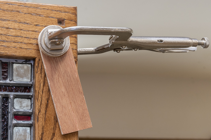
After the latches are finished to match the cabinet they are screwed in place and a strike plate attached to the door.  The strike plate location is marked by putting it along with the mounting screw pointing out against the latch where the magnet holds it in place.  A piece of painter’s tape is applied to the door covering where the plate will be attached.  The door is then pressed against the screw whose point marks the plate’s location on the door.  The tape lets me clearly see where the screw makes its mark.  The photo below shows the latch installed.

The last bit of work is to run the pick around each piece of glass in the doors inside and out doing a final trim of the grout.  That’s followed by a thorough cleaning of the glass and zinc using denatured alcohol then polishing with a soft cloth.  No shots of that as in the photos the windows look pretty much the same before and after. 

I have to say that this project took quite a bit of time to complete.  It was not a real surprise as there were a lot of time-consuming details in the design.  I knew that going in but it’s those details that really give the finished pieces their presence.  Overall size of each cabinet is, 6’-7” tall X 38” wide X 17 ½” deep.  I can just get it through a regular 6'-8" tall door with an inch to spare although If I take off the top that will give me another 1¼”.  Once the lacquer finishes gassing off, I will move them into the house.

In order to showcase the stained glass panels and really bring them to life they need to be back-lit.  I want to use LED strip lighting attached inside the cabinet to do that.  It’s just that so far, I can’t find the right LED strips.  The photo below shows the desired effect when I hung an LED shop light inside.  When I find the appropriate lights and get them installed, I will update this post.


Monday, December 23, 2019

FLW Cabinet - #30 Peg & Glass Installation

Before installing the completed pegs, I want them to set for a week or so to allow the lacquer to harden some.  Since the installation will be a press fit, I want the lacquer hard enough to resist scratching during installation.  In the meantime, it’s on to grouting the second cabinet window.  In the photo the blue tape marks the last pieces done so it’s easy to keep track of how far I have gotten.  Grouting is tedious work, probably the worst part is when you are all done it looks the same as before you started.

With both glass panels grouted at last (WHOPEE!!) I went back to work installing the pegs.  First step is to go through sorting all the pegs so the grain matches when looked at them from the end.  Since the intent here is to make the pegs look like through tenons the grain needs to be consistent between the two.

The peg installation process is similar to installing the faux tenons except at a smaller scale.  It follows the same first couple steps as the faux tenons with the glue applied inside the mortise and the pegs started by hand.  That’s been done in the photo below where you can also see a couple of red dots on the pegs.  They are there as a reference mark so when installed it’s easy to see if they are mounted in the correct orientation.


Next the spacer that will hold the pegs a consistent distance proud of the legs is clamped in place.

Rather than use a rubber mallet to hammer the pegs in place I use a large parallel clamp to gradually pull the pegs into position.  This is what that looks like when ready to tighten the clamp.

When the face of the clamp is tight against the spacer they are at the correct depth.  Using the clamp provides great control in applying just the required amount of pressure.

Here is what the completed peg installation look like. 

When the pegs on the opposite side are installed a second thicker spacer is set over the already installed pegs (right side) like this.  That’s so when the clamp is tightened down it does not press the already installed pegs further into the mortise.

This is what the top of the case looks like with the leg pegs installed.  As you can see the door pegs still need to be done.

Installing the stained glass panels in the door is next.  That’s started by putting down a piece of cardboard so the door and glass assembly can be moved around on the workbench without scratching the finished door.  With the door set face down two layers cardboard are cut to fit inside the wood door frame.  These act as spaces to fill the gap between the zinc came and the front of the door.

The glass panel is carefully laid into the rabbit cut into the inside of door then measurements are taken on the spacer’s thickness to fill in between the zinc window frame and the rabbit shoulder.  In a smaller door I probably would have just set some small pieces to hold the glass in place then applied the retainer clips to hold the window in place.  However, since this is a large (26” X 66”) panel I wanted the door and glass panel locked tightly together acting as a monolithic assembly to reduce the chance of the door frame sagging.  My measurements showed that the long side spacers needed to be 3/32” thick and 7/64” wide.  Pretty small pieces to be cutting on a table saw.  My process is to cut the 3/32” pieces a little thick out of a ¾” board then take them down using the thickness sander until I ended up with 3/32” X ¾” X 66” long blanks.  To get the 7/64” width I cut them on the table saw but because they are so thin it’s not safe to cut a single thickness.  On the other hand, trying to hold multiple pieces together and run them through the table saw is a lot like herding cats.  The solution I used is to apply tape to three pieces to hold them together then run the stack through table saw.  Here is what the stack looked like taped.  As an additional measure to minimize the stress during the cut I switched the saw blade to a thin kerf rip blade.

Being a firm believer of keeping my fingers away from the saw blade I used a push block or two to move the stack through the saw.

The zinc came frame around the window is not exactly straight and parallel to the door frame.  As I wanted a snug fit all around some trimming using a hand plane and scraper is required.  Once fitted the pieces were removed, labeled for location and stained to match the door.  After drying overnight, they were put back in place.  I did not glue them in but will rely on a friction fit to hold them in place.

Last step to hold the glass panel in place it to install the glass retainers.  To make sure the panel stayed put two are installed at the top and bottom along with five on each side for a total of 14.  Here is what it looks like with one in place and a close view.

All of the pegs have been installed except for the ones in the door.  I had left those out while installing the glass panel since I was worried that they might get dinged up while moving the door frame around plus I needed the frame flat for support.  That’s in the next and last post for this project.

Next up – Door Pegs, Latch & Lighting

Monday, December 16, 2019

FLW Cabinet - #29 Pegs

Before I start working on making all the pegs I decided to see how the door frame would look set on the grouted window.  It fit just fine and the stain color goes well with the glass.  After looking at the backside on how the window set in the door I made a decision on exactly what type of retainers and got them ordered.  The install will be covered later.


Here is a section drawing showing how the pegs will fit in their holes in the legs.  Only ¼” of the exposed end will be stained and finished.  The rest is left raw for good glue adhesion.

First up on the pegs is to make the blanks they will be cut from.  All told the 64 pegs that go in the ½” square holes will require about 5 ½ feet of material.  To that I need to add some extras for ones with flaws, the saw kerfs and waste when the individual pieces get too small to handle.  All that adds up to about 4’ or in total 9 ½’ so I made 10 ½ feet.  It’s way easier to make extra as long as the equipment is set up versus going back and making a 12” piece because you were a few pegs short. 

The blanks are made from leftovers saved during the build process.   They get ripped to about 1/16” oversize on the table saw then gradually reduced down using the thickness sander.  The mortise machine makes ½” square holes that are really .497” and to get the pegs installed they need to be a little undersized.  In this case a little is 2 thousandths of an inch or less than a sheet of typing paper.  Anyway, here are what the blanks look like ready to be turned into pegs.

The process starts by beveling the end of the blank at a 45-degree angle.  A disk sander is used to rough them out.  This shows the fence setup which gives me a consistent angle.

The problem with the disk sander is the disk itself is pretty coarse, like 60 grit coarse.  To smooth the surface out a 220-grit random orbital sander sheet is set against the disk.  The disk is rotated back and forth by hand maintaining the angle and smoothing the beveled facets.

Just in case I overshoot the size of the facets making them too big and need to remove a bit from the end of the blank a temporary fence is clamped to the disk sander to hold the blank at 90 degrees to the disk.

Here is what a finished beveled end looks like ready to be cut to length.  Since I have not come up with a good way to add a stop to control the size of the bevels they are all done by eye comparing each one to the original master sample.

Cutting the pegs to length is done with a fine-tooth cutoff blade on the table saw.  A stop block sets the peg length and a backer board minimizes blowout when the blade exits the cut.

Before staining I need to mask the end of the peg off to keep it clean.  Since there is not a lot of leeway in where the masking tape goes a line is added for reference using an adjustable square.  If you look closely, you can see it on the peg.

To help get the peg started in the hole the heel of the peg has a little taper added by making a pass across some 80-grit sandpaper clamped to the saw extension and ta-da one peg ready have masking tape applied then stained.  Getting everything set up to do the 70-piece production run took a while so the first peg took about three hours to do. 

However, once I got into a rhythm working to make groups of 10 it only took a little over 90 seconds per peg.  Here are what all the pegs look like ready to stain.  There are two sizes 1/2" and 3/8", the majority are the ones that go in the legs and others are for the doors.

The first coat of stain went on pretty quick (top photo), now I just need to let it dry before adding the gel stain (bottom photo).  Because the smaller pegs are so little, I had to hold them with the needle nose pliers to apply the gel stain then wipe it off.

Applying the lacquer is next and presents a bit of a problem.  If I lined up the pegs similar to when they were stained then made a pass with the small airbrush the air blast would blow them all over the place.  Not exactly conducive to getting a quality finish.  To hold them securely in place I plan to set them in a sacrificial mortise and then spray.   The mortises will be cut in the plywood scraps using the mortising machine to cut the holes.  Here is what the mortising machine looks like set up.

Here are most of the pieces needed.  After I took this photo, I counted the number of holes and was short about 30 so made some more.

To get ready to spray lacquer on the pegs the blue masking tape needs to be removed and the pegs pressed into the plywood holders.  The depth is controlled using a simple spacer then a scrap piece of plywood is used to push the peg flush with the top of the spacer.  The photo below shows the progression from taped peg to one pressed in ready to be sprayed.

Here is what the setup looks like for spraying with the small air-brush.

After spraying on 2 coats the pegs look good but I am going to give them one more coat to provide a little more wearing protection.

After an overnight cure of the last coat of lacquer I popped the plugs out of the holder.  Here is one of each plus a penny for scale.

Next up – Peg & Glass Installation

Monday, December 9, 2019

FLW Cabinet - #28 Grouting the Stained Glass Panels

This post falls outside the general woodworking I usually cover in this blog but is an integral part of this project so here goes.

When I built the stained-glass panels that will go in the doors back in the late 90’s the glass was not grouted or cemented in the zinc came.  That’s because since they were mounted in sliding glass doors any moisture condensation that accumulated between them and the door glass would have a way to escape.  That worked well in that situation but now since they will be mounted in an operating cabinet door, I need cement or grout the well over 500 pieces of glass per window solidly in place in the zinc came to help provide rigidity for the door assembly. 

The process starts out by laying one of the panels on a piece of carboard to protect my workbench as cementing or grouting can get a bit messy.

In their original installation in the sliding glass doors there were 6 copper tabs on each panel that were used to mount the panel in the door.  The left photo below has a pencil pointing to one of them and the right is a closer view of the same one. 

Because they will not be needed when they get mounted in the doors they need to removed.  Since they were soldered on a little heat with the soldering iron removes them.  In the left photo I am heating the tab and in the right one it has been removed.  I did do a little cleanup on the joint after the photo was taken to make the result look a little better.


Next is to do the grouting which will fill the gap between the zinc came and the glass.  The drawing below shows a cross section through a typical piece of zinc came plus the glass.  The left side is before grouting while the right shows the final grouting.  This will anchor the glass in place and make the whole window more rigid and stronger. 

It has been a long time since I did any window grouting and the materials have changed since then.  Since nothing was available locally, I was left with ordering the material online.  Previously the grout was like cake batter while the current grout is very thick, more like a putty.  Because of the material change the grouting process changed too.  This meant there was a bit of learning curve (2 days) before I got any proficiency in putting it on.  With that in mind here is the process I am currently using to install the grout.

Step 1: Using a 2” wide putty knife a small quantity of the grout is applied to the glass/came joint and pressed into it until no more can be packed in.  For me holding the putty knife near the tip with both hands gives good control and allows me to easily apply sufficient pressure to really pack the material in.  One thing to remember is that the idea is to fill the gap between the glass and the came so the direction of the applied force is parallel to the surface of the glass.  Minimal downward force against the glass is used to prevent scratching or worse cracking a piece of glass.  

This worked well where the lengths of the came were longer than the putty knife.  However, there are a lot of narrow or just small pieces in the window.  Moving to a smaller 1” wide putty knife helped but still did not allow me to get in the smaller spaces.  My solution was to take a couple scrap pieces of wood and rip them down to half and quarter inch wide strips then bevel the end.

Here is what it looks like when I get that done in an area.  For this window a square foot takes just under an hour.  Areas with mostly large pieces take less time.


Step 2: Trimming the grout is next.  That cleans up the joint and gets rid of the excess grout.  There are a couple of specialized tools that can be used or in my case I took a scrap of oak and turned it to the profile I wanted in the lathe creating my own “pick”.

The pick is run around each piece of glass and.  In use the pick is held 90 degrees to the glass tight to the came then run around each piece of glass which trims off most of the excess grout leaving a fairly nice edge.  At the same time each glass to came joint is checked to make sure it has grout and was not missed.  Any missed spots are fixed.


Step 3: Cleanup is next.  There are a couple of materials that can be used to clean the excess grout from the came and glass.  One is whiting or calcium carbonate and the other is very fine sawdust.  The sawdust is not what you would get from a tablesaw or similar tool but the very fine, almost flour-like dust that is the result of sanding.  As it just so happens my thickness sander makes this type of sawdust in copious quantities that is sucked up by the dust collector.  When starting the grouting the dust collector bag was about half full which gave me over a 5-gallon bucket of just what I needed at no cost. 

Here is what the window looks like after liberally sprinkling the sawdust over the just grouted area.

A moderately stiff natural bristle brush is used with modest pressure.  Too much and you risk the chance of breaking a piece of the glass.  The sawdust and scrubbing cleans off the excess grout turning the sawdust a darker color.  When it looks like the excess grout is mostly combined with the sawdust a shop vacuum is used to remove most of the sawdust/grout mix.  Some will still be packed into corners.

Another pass with the brush is done to remove as much of the sawdust/grout mix as possible then vacuumed away followed by gently sweeping the surface with a soft brush and blowing it off with compressed air.  Since I generate more sawdust than I can use I don’t bother trying to reuse it. 

Step 4: Tool or detail the came/glass joint.   With the sawdust and excess grout removed I check again for any missed areas or grout that needs to be fixed.  Once any repairs are done it’s time to finish the came to glass joint.  At this point the grout will probably have a little bit of a bevel between the glass and the zinc came.  Below on the left is what that looks like and on the right is what is wanted. 

Step 5: Last step is to take a soft cloth like an old cotton tee shirt and clean any of the odd remaining spots of grout off.  Below is what a finished section looks like which is pretty much the same as before.  Start to finish it takes about an hour and 20 minutes per square foot of window.  There is a bit over 12 square feet per side of window so that works out to roughly 16 hours per side.  Yes, you have to do both sides.

As mentioned earlier I made a rough guess on how much I needed and ordered the largest size available.  As it worked out, I used about ¾ of the container on one window so will need to order more.  That’s OK as I am really tired of grouting so will wait on doing the second window and move on to making all the pegs.

Next up – Pegs