Router Plane

Monday, March 30, 2020

Cam Clamp - #3 Making the Cam, Fitting the Pins & Finishing

The cam is next, the rendering shows it both installed and by itself.

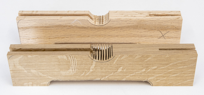
When making the blanks for the cams I made them about 1/64” thicker than needed for a couple of reasons.  First, if they warped any I had some room for correction and second is to give me a little extra just in case the dado for them ended up a little wide.  Well, the pieces didn’t warp but the dado ended up being about .004” undersize.  In order for the cams to move freely they were thinned down so they are about .006” smaller than the dado.  That’s done by placing the cam blanks on a carrier then running them through the thickness sander.  The bottom photo shows the blank in the carrier.

The cam pattern is traced onto the blank, cut out on the bandsaw, rough sanded with the disk sander then hand sanded smooth.  Here is the pattern, blank and shaped cam.   It’s not completed as plans are to soften the edges with either a chamfer or radius, I just don’t know which yet.  The small hole in the cam is the same size as the marking punch which allows me to do testing for the fit.  The cam and the jaw get drilled out to ¼” next followed by the final fitting to get the right amount of travel for the pressure pad.

Routing a little chamfer on the jaws and the cam come next.  Here is how that looks while being done on the router table. 

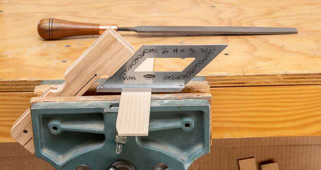
All of the edges can be done except for the upper and lower corners where the aluminum bar goes through the end of the jaws.  They are done with a fine-tooth file.  To do that they get clamped in the bench vice at a 45-degree angle.  That allows me to use the file level and not worry about what angle it needs to be held at.  I can just concentrate on getting the right depth cut.

This is a closeup of the chamfered edges.

Measuring the aluminum rods for the pins that will secure the jaws to the aluminum bar is next.  A dial caliper is used set to the thickness of the jaws.  The sharp point of the left jaw scribes a line in the softer aluminum for the required length.  The black arrow points to the scribe mark and helps me find it when getting ready for cutting.

The rod is clamped in a metal working vice that has a couple of thin boards that act as a cushion between the vice’s jaws and the rod.  They keep the teeth in the jaw from marring the rod.  The actual cutting is done with a hacksaw.  The top photo shows the vice and rod while the bottom one shows where I have started the cut.  If you look closely you can see just a tiny bit of the black mark on the right side of the cut.  That’s how much oversize the rod is cut to allow for swaging and cleanup.


After the pin is cut then filed smooth and square it’s ready to be installed.  Below shows the prepared pin and bottom jaw.

Installation is done by lightly tapping the pin in until it’s started then driving it in place until it is a little proud on both sides.  In the photos below you can see how the pin stickes out just a tiny bit.  Next is to sit the piece pin side down on the anvil part of the vice and give the upturned pin end a good whack.  That spreads the pin just a little increasing its diameter and locks it in place.  

Once the pins are set a drop of cyanoacrylate (Super Glue) is added as insurance they won’t loosen. They are then filed smooth with the jaw’s face and sanded to remove the filing marks. 

At this point all the pieces are ready for Danish Oil finishing.  Here are what the two clamps now look like.  As you can see the cams are not yet installed.  That’s because if they were pinned in place then it would be next to impossible to finish them.  Once finished the ¼” pins will be cut and installed just like the others.  I do realize that the filing and sanding of the pins will probably mess the already applied oil finish up some around them.  This is not a problem because the oil finish can be reapplied easily now or in the future if the clamps get banged up and will blend in just fine.

Putting on the Danish Oil really brings the color and grain out.  This photo is after I have put on two coats.  That’s it until they have had a chance to cure for a few days and I take a close look to see if it’s time to install the handles then go back and add another coat.  In looking at the clamps the next day, they needed a third coat. 

Once that was applied and left to cure for a couple of days the axel for the cam gets cut and installed just like the other pins in the jaws.  Surprisingly when filing the axel flat the oiled finish on the jaw was hardly scratched but for uniformity, I gave it another coat of oil.  
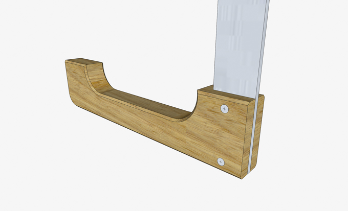
When that had cured for a couple of days it’s time to put the pieces together and add the last pin.  This pin goes at the top end of the aluminum bar to keep the upper jaw from sliding off.   It’s not very big at only 3/8” long.  The first difference is that because it’s not flush, I needed to put it in a scrap to file the end square and flat.

Because the edge of the pin is very sharp it needs to have a small chamfer added so it won’t cause problems in use.  That’ done on the lathe by chucking the pin up in a small chuck then using a file to add the chamfer.  In the photos below you can see the pin chucked up and below that on the left is the squared off pin end while on the right is after the chamfer has been added.

Drilling the hole in the top of the bar is next.  Once laid out a punch is used to make a dimple that acts as a starting point for the drill keeping it from moving around.

After the hole is drilled the pin is inserted, centered in the bar and is ready to be locked in place.  To do that a spacer the thickness the pin is expose is set on the vice/anvil.  The pin is set in a hole drilled in the spacer and the exposed pin struck with a hammer causing it to expand in the hole locking it in place.  For insurance the clamp is flipped and the other end of the pin gets the same treatment. 

There remains only one item before they are finished and that is a cork cushion on the jaws.  I had been looking around locally to no avail but found some on-line that are 12” X 12” X 3/16” thick pieces in 4-packs at a reasonable price.  That gives me about 50 times the amount of cork I need but they do the job and I can probably use them on other future projects.


Here are the clamps showing how they would clamp things together. 

All in all the build was fairly easy and did not take a lot of time.  It also put to use the leftover aluminum bars that I had.  Now they will go in the clamp rack along with the rest of my clamps.

Monday, March 23, 2020

Cam Clamp - #2 Wood Selection & Shaping the Jaws

The actual build of the clamps starts by me going through my leftover box to see what material I had.  Not surprisingly I found pieces of Cherry, Red & White Oak, Hard Maple, Walnut plus a piece of Locust.  As an experiment using similar woods, I decided to make one clamp out of the Red Oak and one out of the White Oak.  One other difference is the Red Oak is flat sawn and the White Oak is quarter sawn.   Looking at the growth rings it’s easy to tell the difference with the flat sawn Red Oak on the left and the quarter sawn White Oak on the right.

With the material selection done the top jaw, bottom jaw and cam blanks were cut a little long and to finished width and thickness.  Set side by side you can easily see how the two oaks look different.

First cut is the slot at the end of the bottom jaw where the aluminum bar will go.  Here is a rendering of how those two pieces will go together.

That’s done using the tenoning jig shown here set up and ready to go.  The detail on the right shows the outer limits of the cut for the aluminum bar.

A shallow test cut is made then the sides are measured to see if the cut is centered.  In this case it’s off center by three thousands of an inch and that’s just fine.   I will mark the outside face on all the pieces so when assembled the bar will be square with the jaws.  Since the pieces are long if the cut was off I could trim the piece and recut.

The final depth is then set and the slot cut in the bottom jaws.  Here you can see what the cut piece looks like along with one in the tenoning jig.   One interesting item came to light is the fit of the aluminum bar in the just cut slot.  Even though both pieces were cut with the same table saw setup there is a .004” difference between the width of the two.  The Red Oak slips in easily and slides along the bar with no problem while the White Oak one is a snug fit and does not slide without a fair amount of effort.  No idea why or what caused it.

Tracing the template onto the bottom jaw is next as shown here along with the aluminum bar set in place.

A Fostner bit is used to rough out the interior arcs in the jaw.  To eliminate any chance of blowing out the back side of the jaw when the hole is drilled the depth of cut is set to stop just short of breaking through.  Here you can see the small gap between the bit and the sacrificial base.

Since the bit is just cutting a partial hole, I clamped the piece securely in place so it would not move during the cutting process.  The top photo shows the setup and the bottom photo shows the finished cut with the thin section at the bottom of the hole. The thin piece is cut free because the rim of the bit cuts slightly deeper than the rest so when cutting from both sides you end up with that thin piece.

To smooth the bandsawn section and the drilled arcs at the ends the oscillating sander is used.  This is similar to the smoothing process used for the templates.  The difference here is that I wanted to use a larger drum starting with a coarser grit as this drum matches the radius of the arc, the pieces are thicker and a lot harder material than the templates.  Using a larger drum required a little different setup than the templates.

Once the rough sanding to shape is done the sanding sleeve is changed out to a finer grit to smooth out the cut.  That’s followed by a trip back to the bandsaw to rough out the outside arc followed up by hand sanding the cuts up through 220 grit paper.  Here are the two lower fixed jaws at this point.  Just out of curiosity I weighed the two samples since they are identical in size and found that the White Oak is about a third heavier than the Red Oak.  The extra weight is definitely not due to moisture content as both have been setting in the storage area for years.

Work on the upper sliding jaw is next.  The general shape is similar but it does have a few detail differences.


The first step is to cut the slot for the aluminum bar which is the same as the slot in the lower fixed jaw except it is cut a bit deeper.  Next is to cut the slot for the cam lever that will provide the pressure to tighten the clamp.  That’s done on the table saw with a ¼” wide dado blade and a stop.  The stop will limit the length of the cut to 4”.

Here is how the stop works to limit the cut.  Note that the piece is upside down and that this slot will end up at the top of the jaw.

After that the template is used to trace the notches at the top and bottom of the jaw.  The bottom notch is made the same way as the one in the fixed lower jaw.  The one at the top is not drilled but rough cut on the bandsaw.  Since the bandsaw blade is ½” wide it can’t cut very tight corners so rather than taking the time to change the blade I cut a series of saw kerfs as shown in the front piece then cut them out giving me the rough shape shown on the back jaw.

Using the same oscillating drum sander setup as with the lower fixed jaw the notches are sanded fairly smooth then finished by hand sanding.

Next is to drill a pilot hole for a screw that will go in at an angle near the back of the notch.  It is to help reduce the chance that when the cam is actuated the upper jaw moving face will not get split.  Below you can see how the ramp I made for the Router Plane worked out to be just what I needed.

Cutting a slot in the upper jaw along with a 1/8” hole is next.  Below you can see the template and the finished slot.  The 1/8” hole acts to spread the stress out across a curved surface helping to reduce the chance of the lower part splitting when the cam applies pressure to it.  I did move the hole slightly when the screw was added which as noted above also acts to mitigate the chance of the piece splitting.  Also, on the left side the punch is in the template for marking the center of the cam axle.

Next Up – Making the Cam, Fitting the Pins & Finishing

Monday, March 16, 2020

Cam Clamp - #1 The Beginning

In 2005 when I was making an acoustic guitar, I borrowed a truckload of these wooden bodied cam actuated clamps from a friend as I only had four of them.  Here is what the guitar body looked like when I was gluing the back to the sides with all those clamps.

I had always wanted more of them but at that time they ran about $25 each which is more than I wanted to spend for a specialty type seldom used clamp.  That all changed when I recently found a plan for them that used a 1” wide by 1/8” thick aluminum bar for the clamp’s spine.  By coincidence I have two pieces of aluminum bar just the size needed.  They are left from when I made the Dining/Game Table for my son.  The photo below on the left is one of my original clamps and the rendering on the right is what my SketchUp drawn plan looks like.  If these work as well as the store-bought ones then I might make some more. 

My first step in making the clamps is to create three templates.  Having ready-made templates on hand will certainly speed things up.  Here is the template drawing that I glued to a piece of ¼” plywood using some spray adhesive used for mounting photos.

First step in cutting out the templates is to drill the various holes around the perimeter of the piece.  I use the drill press setting the depth stop so that only the point of the bit comes through the piece.  Here is what that looks like.  That’s done to eliminate any possible blow out on the back side when the drill breaks through there.

The hole is finished up by turning the piece over, aligning the bit point with the hole on the backside and drilling through meeting the hole drilled on the front.  This photo shows the drilling completed with a thin piece just setting in the hole.  It is pushed out giving me a hole with nice smooth edges.

This is the template with all the perimeter holes drilled.  On one of the holes I applied a little too much pressure when starting and the bit grabbed the paper tearing out a little.  That’s not a problem as all I needed to do was extend the base line in pencil.  There are still six holes that need to be marked but those will be addressed later.

After ripping the templates to width on the table saw and cutting them to length on the chop saw I used the band saw to cut close to the lines that delineated the inset area between previously drilled holes.  In order to smooth the bandsaw cut and bring the opening right to the line that was left from bandsawing I used the oscillating sander.  Below are the two setups used.  The only difference is the size of the sanding rod used.  Its size is determined by the depth of the recess. 

The last bit in these templates is working with the last six holes mentioned earlier.  Of them there are three that really need to be located very accurately.  Two are for pins that lock the top jaw in place on the aluminum bar when the locking cam is used.  The third is for a pin that the locking cam rotates about also located in the top jaw.  The remaining three holes locations are not quite as critical.  One in the top jaw is at the end of a bandsaw cut to reduce the chance of the jaw splitting when the locking cam rotates and two are for pins that lock the aluminum bar to the bottom jaw.

If I drill the holes in the template and use it along with a bit to drill to make the holes in the jaws then over time the drill will chew up the template impacting the accuracy.  Not a problem for most of the holes but I can see it being one for the three described above.  To avoid this the template will be used to punch a centering mark in the jaws with a pointed pin.  That mark will then be used locate the holes. 

The process starts by making the pointed pin from a 4-penny finishing nail.  The nail head is cut off then mounted in the lathe where the cut is filed smooth and the edges beveled.  Next the pin is flipped and the nail’s faceted cut point is filed to a smooth conical point.  That’s what is shown below.
Next after carefully marking the center point of the holes on the template with a center punch a 1/16” hole is drilled in the template. 
Last, because a 4-penny nail is just a tad larger than 1/16” the pin is chucked up in the drill press and spun through the template.

Last a template for the cam is made completing the three required templates.  Here are all three done and ready to go.

Next Up – Wood Selection & Shaping the Jaws

Monday, March 9, 2020

Router Plane - #6 Three More Handles & Two Knobs

As I started working on the second handle it occurred to me that a template with the needed measurements on it would speed things up and help reduce the chance of a measuring error.

From this point on the process for making the remaining handles is the same as the first one although it does go a little faster at about 2 hours each.  It seems the closer I get to the Pattern #1 match the slower is goes as I want it as close to a perfect match as I can get.  Here are the four matching handles and have to say being very careful and frequently checking my progress paid off.  After all there is no “Undo” button if the cuts are too deep.

Cutting the 7/16” threaded rod that will be epoxied into the handles is next.  I cut them to length using a jig saw with a metal cutting blade.  A hack saw could have been used but the jig saw is easier.   Here the rod is clamped into the vice ready to be cut.  One other thing, if you look at the right side of the vice you can see a scrap piece of wood with a clamp on the end.  That acts as a spacer to keep the vice jaws parallel when it is tightened.  The clamp on the spacer keeps it from falling to the floor when the vice is loosened.

However, after cutting the rod its threads and the cut ends are messed up and need a little help before they are usable.

The cleanup is done on a grinder.  The nuts on the rod give me a place to hold on to it and set the grind angle.  Once the grinder is running the rod is turned while being kept at the same angle.  Once ground the rod is ready to be used.

Epoxying the rods into the handles is next.  A 5-minute 2-part epoxy is used.  Here are the completed handles clamped up for curing.  Clamps are used to hold the rod in place while the epoxy cures.  The clamps keep the rods fully inserted in the handles as I have had rods want to creep out before the epoxy sets.  I think it’s due to the epoxy sealing around the rod causing air to be compressed as the rod is pressed into place.

Once the epoxy is cured the handles are removed from the clamps and screwed into the inserts in the body.

The last item before applying a finish is to make the blade locking screws.  I had ordered steel knurled knobs but when I changed the size of the body they were too short.  While working on the square tube I got to thinking that I wanted a material softer than the tool steel of the router blade to apply the locking pressure and brass fits the bill.  That’s why the insert is also brass so as to not have dissimilar materials which could introduce galvanic corrosion.  The knobs start by cutting a ¾” cube from the Texas Ebony base cutoffs.  Here is the last cut being made on the bandsaw.  Since there is no way I am going to get my fingers that close to the bandsaw blade I use a screw clamp to hold the piece while being cut.

Using a centering square, the center of the end is located, center punched and it’s ready for the drill press.  The hole will be used for mounting the piece on the lathe.


Before mounting on the lathe, the disk sander is used to round off the corners to help make the turning easier.  That’s done since the attachment is a little delicate and the less stress the better.

The blank is attached to an oak mandrel via a screw that gets run into the hole drilled in the blank’s center.  The oak piece is then clamped in the 4-jaw chuck and the turning can begin.  Here is the blank after it has been turned round and you can see how it all fits together.

In order to provide a better grip to the knob 12 recesses will be cut around the knob’s perimeter.  That starts with marking the blank into 12 equally spaced sections.  The lathe has an indexing feature that locks every 30 degrees giving the 12 sections.  The photo below shows the threaded rod near the left side of the photo run into the detent in the lathe shaft and the section marks on the knob at the lower right.

The recesses are made using the oscillating drum sander by very carefully aligning the white mark on the knob with the centerline of the sander then gently pressing it against the drum.  The piece of plywood that the sander drum is coming up through has a hole the size of the drum and is clamped to the sander’s cast iron top.  It’s so I have full support for the knob when sanding.  In the right photo you can see the end result of the process with the recesses made but in dire need of some additional sanding to make them smooth. 

However, before that I need to go back to the lathe and drill a hole in the base of the knob where the threaded rod will go.  This is the setup at the lathe ready to go.  There are a couple of things that need to be explained though.  First, is why the final sanding of the recesses are not yet done.  That’s because if when the knob is clamped in the 4-jaw chuck the recesses get dented I haven’t gone through all the work finish sanding them only to have to do it again.  Second, is the narrow strip of wood held in place with masking tape backing up the knob.  That’s so I don’t have to tighten the chuck down so much which reduces the chance of denting the knob.  Without it the chuck has to be tightened down enough to keep the knob from getting pushed into the chuck’s jaws when drilling the hole.

Once the hole is drilled, I can start hand sanding which starts with a finer grit tube from the drum sander.  Finer grits of sandpaper are used ending up with 320 grit paper until all the scratch marks are gone.  The knob on the far left is a prototype and here is used to give me a better grip during sanding. 

With the knob completed here are a couple of views of the project completed except for finishing.


Next Up – Finishing & a Stopped Dado