Router Plane

Monday, December 27, 2021

Sanding Block - #3 Drilling Concentric Holes, Turning Dowels & Brass Inserts

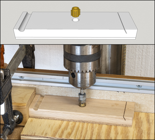
With the fence distance set to center the drill on the joint between the base and upper stack another stop is added.  Its location is found using the center finder to set the left/right location.  Here the stop has been set, the center finder removed and the drill installed.  Not shown in the photo is a depth stop set so the bit just breaks through into the piece of plywood under it.

The photo below shows the result, a half circle cut in the top and base.

The next step is to make the dowels that will get glued into the base later on.  The top photo shows the dowel and where it will be glued in the base.   I will be making the dowels because I want them to be made out of a matching material and because the need to fit perfectly where they go.  Making them starts out with a ½” square blank which is about the smallest size that will fit in my lathe’s chuck and about a foot long.  There is a problem with trying to turn a foot long piece down to a 5/16” dowel.  Turning a piece that long and narrow is not all that rigid so when turning it can flex and chatter or generate sympathetic vibrations.  Both prevent a getting a smooth circular dowel.  The fixes available to are to either cut the blank down into shorter pieces or insert it through the hollow spindle in the lathe headstock.  A steady rest can be bought that uses wheels in frame to put pressure on the blank but I don’t have one.   Fortunately, my lathe has a hollow spindle unfortunately, it’s 5/8” in diameter and you can’t put a ½” square blank though a 5/8” hole.  Almost but not quite.  That brings me to the bottom photo which shows where I rounded the corners of the blank using a 1/8” router bit.  That’s all it took to make it fit.

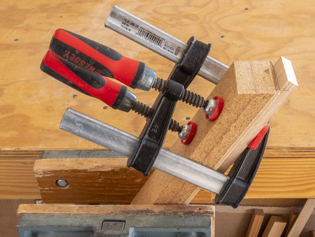
Here is what the blank looks like mounted in the 4-jaw chuck on the lathe.  After mounting I turned the end to small rounded nub which will get used next.  Note how there is not much of the blank sticking out of the chuck so as to minimize any flexing. 

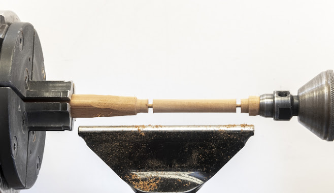
With the nub turned the blank is extended out so it’s just longer than my shortest tool rest and set into the live center in the tail stock.  This live center has a removable center pin which when taken out leaves a cup that the nub fits in.  With the blank supported at both ends and being fairly short the chance of having problems during turning is greatly reduced.

After turning the blank to a rough cylinder, I use a 3/8” wrench as a guide then using a parting tool shave the cylinder down until the wrench just slides over it giving me a 3/8” diameter reference point.  The same thing is done at each end of the dowel then the excess is turned down flush.  Now I have a 3/8” constant diameter cylinder and only have to take off a little more to get to the finished dowel diameter.

Last, a thin parting tool is used to cut the finished dowel off about 1/8” long.  Here that’s almost done.  When parted free a little sanding cleans up the ends.

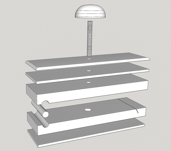
Next are four separate drilling operations for the Knob and threaded rod that will lock the sandpaper in place.  Here is a drawing showing most of the finished holes.

First, with the dowel in place, shown with the arrow at left end of sanding block, for registration of the base and 3-layer stack the center finder is used to pinpoint the hole’s location.  As before the fence is set and a stop block is added so the 5/16” hole gets drilled in the same place in all the sanding blocks.  The hole goes only through the 3-layer stack and just into the base.  That’s so the brad point drill leaves just a tiny dimple in the base which will be use to locate a different hole later on.

Second, the underside of the top 3-layer stack gets a 1/8” deep counter sink made using a ½” diameter Fostner bit.  By carefully making sure the original hole is centered in the piece I can flip the 3-layer stack over and using the same stop block/fence setup get a countersink concentric to the original hole.  The reason for the countersink will be covered later.

Third, without moving the stop block/fence setup the base is set back in its original position.  A 10mm bit is installed to drill a hole for the threaded insert.  If everything has gone right the tip of the bit should align exactly with the dimple from the hole drilled in step one.  Before drilling the depth stop needs to be set so the point of the drill stops right before it goes into the cork.  Good news is the alignment was right on for all the five bases.

Fourth and last the 10mm hole in the base gets a small chamfer cut.  This is to ease the entry of the threaded insert as it is installed preventing splintering at the starting point.

Temporarily installing the threaded insert in the base is next.  The insert (top photo) is made out of brass and has a wood thread on the outside while the inside has a ¼”-20 machine thread.  This allows the threaded rod that’s part of the knob assembly to be put in and taken out frequently without stripping out the wood.  The bottom photo shows the insert being installed.  The drill press is used to make sure it starts square and plumb.  A critical point is to use your hand to turn the chuck to install the insert and NOT I repeat NOT turn the drill press on to screw the insert in.  If you do that, things will go bad in a hurry not ending up well at all!  An added bonus is being able to use the stops already set up to locate the base.

In this closeup the wood threads are visible on the outside of the insert.  The multiple nuts on the inserting shaft are used to put more friction between the insert and the bottom nut than between the insert and the base so the insert can be removed.  Once run in the insert is removed to be installed later.

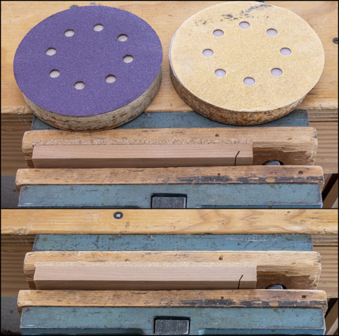
Because the insert it taller than the base I need to grind it down some.  The photo on the left shows one before grinding and the one on the right after grinding which will be installed shortly.

Next Up – Installing Insert, Gang Routing & Knobs Part 1

Monday, December 20, 2021

Sanding Block - #2 Angled Cut, Cork Base, Final Sizing & Locating Dowel

Cutting the 60-degree angled notch in the base that holds the sandpaper is next.  That’s shown circled in red on the completed prototype.

To make the cut a laminated MDF and ¼” plywood block leftover from another jig is cut at a 60-degree angle on its end.  This is clamped in the bench vice with the 60-degree cut parallel to the floor so I am working on a horizontal level surface.  It will act as a guide while I hand saw the slot with a thin Japanese pull saw.  Once the cut is laid out the base is clamped to the guide as shown in the photo below. 

Here is a close-up of how that looks.

With the base clamped in place the Japanese pull saw is laid flat on the beveled guide.  It is held in place by two of my fingers lightly pressing down on the blade as I saw cut the slot.

Once the first piece is cut it’s used as a template to mark the rest of the bases.  That’s done by clamping a framing square to the workbench, setting the template in place then adding the next piece to be cut adjacent to it and using a square draw a line where the cut gets made.

To make sure the base is parallel with the angled jig a scrap is temporarily clamped to the jig to act as a stop, the to be cut base held tight to it, the pencil line for the slot aligned with the end of the jig and the base clamped to the jig.  Here that’s all been done.  Next the temporary stop gets unclamped, removed and the cut made.  The saw is on the workbench ready to go.

This closer view shows how the pencil line for the slot gets lined up with the end of the jig.

Gluing the cork onto the base is next.  Below is the stack of the slotted bases and the stack of cork that has already been cut.  The glue-up process is the same as when the three layer tops were glued together earlier so I won’t go through that again.

Once the cork/base glue joint has cured overnight the best long edge of it and the three-layer top part gets sanded with 80 grit paper and then 120 grit. The top photo shows the 80 and 120 grit sanding disks with the unsanded cork/base part.  The bottom photo is after sanding.   This one sanded edge is to make sure there is a nice straight smooth edge to work off of when ripping to the final width.  That’s done on the table saw in two passes.  The first pass is done by placing the good edge up against the fence so the opposite rough edge gets trimmed making the glued-up layers flush.  After all the pieces have had one edge cut the fence is reset for the final width, the pieces flipped end for end so the just cut edge is against the fence and the sanded edge gets cut.

With all the pieces cut to width they get trimmed to their final length.  That starts by using the big disk sander to sand the cork flush with the end that has the slot in it.  A miter fence is used to keep the end square as shown below.  The cork sands easily so it goes really quick.  I did not use the chop saw because the distance the slot is set back is critical in making the sandpaper fit in the block and didn’t want to run the risk of taking too much off.

The final trimming to length is done on the chop saw.  First, all the three-layer top stack pieces gets one end trimmed up so all three layers are flush.  Last, a stop block is set to the final length and the untrimmed end on all the pieces gets cut.  If you look close in the photo below there are four layers in the stack.  That’s because the bottom layer is a sacrificial piece so I get a better cut edge when the saw blade exits the part.  It’s not a huge problem with the three-layer piece shown since that edge is going to get rounded later on.  It’s also not to critical with the cork/base piece since the cork is going to get sanded a little thinner and that should clean up any problems but it’s better to be safe than sorry.

Next is to sand the cork on the cork/base pieces down a little.  It’s 3/16” thick and I need to take it down to 1/8”.  To do that it’s a simple matter of running the pieces through the thickness sander until the base and cork sandwich is 5/8” thick.  With that done this is what the five sanding blocks look like.

Drilling the 5/16” hole in the base and the upper three-layer top stack for the dowel is next.  The dowel and the slot are primary parts for clamping the sandpaper to the base.   The drawing below shows the dowel highlighted. 

The hole the dowel goes in needs to be very accurately located and I don’t trust the split end of a twist drill or the end of a brad point bit to give me the dead center of the hole.  On my “to-do” list of things to make was a center finder for the drill press and now seemed like as good a time as any.  The top photo shows what it looks like.  It’s made from a straight 20 penny nail.  Testing is easy, chuck it in the drill press then turn the drill press on.  If it wobbles it’s not straight.  Once a suitable blank is found the head gets cut off and it gets chucked up in the lathe.  The shaft is lightly filed to remove any irregularities, sanded and polished with steel wool.  One end is rounded over and the other gets filed to a point.  When done it’s back to the drill press to check and see if it runs true (no wobble of the point) which it did.  The bottom photo shows it in the drill press ready being used.

Here is a close up once the fence has been adjusted so the center finder’s point is dead center on the joint where the two pieces come together as evidenced by the little dimple the center finder made on the joint.  Next is to set a stop block so the center finder is on the pencil line.

Next Up – Drilling Concentric Holes, Turning Dowels & Brass Inserts

Monday, December 13, 2021

Sanding Block - #1 The Beginning, a Prototype & Getting Started

While making the Greene & Green end table I found myself using all sorts of wood scraps to wrap sandpaper around to act as a temporary sanding block.  In my hand tools are a couple of third sheet hard rubber sanding blocks that are older than dirt.  They are cracked and brittle plus don’t really hold the sandpaper snugly so the paper always slides around in use.  As a result, they only rarely get used anymore.  With that in mind I decided it was time to see what I could come up with as a shop built sanding block that would hold the sandpaper securely in place, be comfortable, allow easy changes of sandpaper and used full fractions of regular 9” x 11” sheet sandpaper.

For most of my sanding either a ¼ sheet pad sander or a random orbital sander is used like the ones below. 

There is no good reason to duplicate the coverage the power sanders provide so after thinking about how I used the sandpaper wrapped scraps a narrower, longer shape emerged.  Working backwards from the regular 9” x 11” sheet of sandpaper gives three 1.833” x 9” strips from a half sheet leaving two ¼ sheet pieces for the pad sander.  After a lot of paper sketches and a bunch of dead ends it was time to draw a 3D model in SketchUp or more accurately about half a dozen different possibilities.  One seemed to be viable enough to start some testing.  Finally, after a good handful of revisions to different parts this is the drawing used to make a full prototype.

Not surprisingly there were a few more revisions made during the prototype build process but, in the end, the final product shown below looks, feels and works really well.  I would like the top knob to have a better grip while being smooth to the touch but don’t have a solution – yet.  If you are wondering why this project blog starts with a finished product it’s because once the design is done and the sequence of operations is finalized, I am going to do a short production run of five more sanding blocks.  That’s so I can have a different sandpaper grit on each one and not have to change the sandpaper out when working through the range of coarse to fine grits.  With that in mind my plans are to do the build explaining what’s going on and also highlighting the items/processes used when making multiple identical parts.

First, since the pieces that go into the sanding block are not very big, I want to work only from material in my scrap box.  Below are the very roughed out parts for five sanding blocks.  There are a total of four different woods; oak, cherry, walnut and hard maple.

With the rough material selected it’s time to bring the individual blanks to a consistent length, width and thickness.  That starts with ripping the two ½” thick base pieces shown below to thickness plus 3/32”.

I normally rip pieces like this down using the band saw.  However, the rough pieces were not thick enough to have anything useful left over so the table saw is used.  The setup is below where the black wing on the yellow magnetic fence will press against the piece being cut to hold it snug up against the rip fence on the right.  They are then run through the thickness sander to smooth the surface getting rid of any burn marks left by the sawn blade and get to final thickness.

The next is to bring the 1/8” pieces shown below to their final thickness following the same process as the thicker ½” pieces.

After that all the parts are cut to their blank size of 2” wide and 7” long.  Below is a photo of the five stacks needed for the five sanding blocks.  Having consistent sizing will make steps later on easier.  In theory when all done, I should be able to swap parts from one sanding block to another without any problems.

Gluing the 1/8” pieces to the ½” upper base is next.  They are shown in the rendering below.  The bottom photo shows them glued up and in one of my two bench vices.  After the first stack goes in the vice a second stack is glued up and put in the other vice.  I used the bench vise because while being closed the vice’s faces do not rotate and that helps keep the three layers in alignment.  The glue used is Tightbond III which is a waterproof glue.  It’s used not because a waterproof glue is required but because I wanted a dark glue line.

After about 20 or so minutes the glue had set up enough, I could scrape it off with a putty knife.  Here that is in progress.  A good edge will be needed when the glued-up blank is cut to its final thickness.  There will probably be a small amount of cleanup needed but a lot less than if the glue squeeze out had not been taken care of now.

In another 20 minutes or so the stack gets taken out of the vice and put in a ganged set of clamps so another glued stack can go in the vice.  Here four stacks are clamped together and will stay that way overnight.  The 5th stack is still in one of the vices.

While the glue is setting up in the vice, I worked on other parts to be used later on.  One of which is a layer of cork.  The cork goes at the very bottom of sanding block to act as a little bit of a cushion between the sandpaper and the wood base.  See the rendering below.  When I built the Danish Cord Seat the cork used for leg glides came in a pack that was way more than I needed so it will get used here. 

As cork is somewhat soft and granular in form, I was worried that just running it though the table saw to size might result in a ragged edge.  To minimize that a plywood block is used as a backer and it worked out great giving me nice smooth edges.

Next Up – Angled Cut, Cork Base, Final Sizing & Locating Dowel