Router Plane

Monday, November 28, 2016

Dining/Game Table - #15 Assembling & Installing the Arm Rail

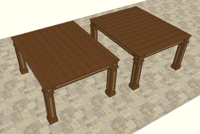
While I wait to see if the pieces for the table top are stable I will go back and work on the arm rails.

Because the table will be disassembled for delivery I wanted to make sure the four arm rail pieces go back together just the way they are now.  To that end I decided to use pocket hole screws to lock the pieces together.  However, before I do that I need to route the inside and bottom edges for two reasons.  First, I will not have to blend the inside face routed edges by hand.  I had enough of that when doing the legs.  Second if I waited until the arm rail was installed the outside bottom edge would be really awkward to get to.  Here is my prototype, note the different radiuses of the round overs.
Arm Rail Test

Process for routing is to clamp a piece face down then route the inside bottom round over with a 1/8” radius bit then the bottom outside edge with a 3/16” radius bit.  With the bottom done I flip the piece over and route a 3/16” radius round over on the top inside edge.  This leaves just one edge and the corners to do after the rail is installed.  More on that when I get there.
3 of 4 Round Over's Done

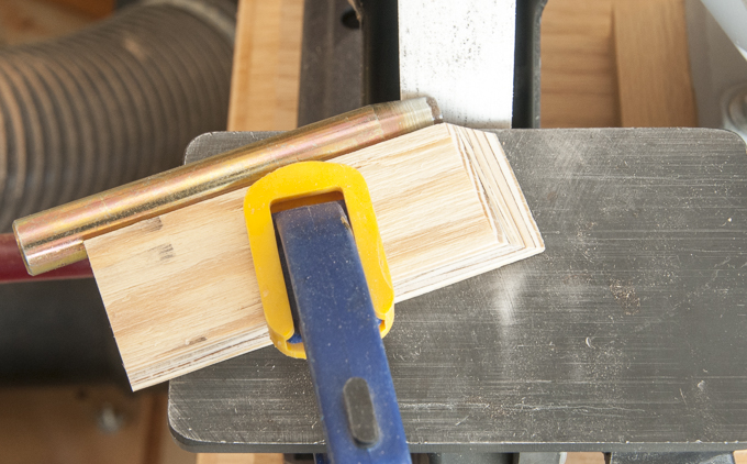
After completing the routing I can start working on drilling the three pocket holes at each miter joint.  Going back to my prototype I slightly changed the location of a couple of the holes for more equal spacing or to move the pocket hole a little farther from the edge then transferred the locations to each piece.
Marking Pocket Hole Locations

With the locations marked I can start drilling.  Only problem is the holes are at a right angle to the 45 degree miter joint which means that when I put the rail in the jig it is at a 45 degree angle and the jig’s clamp will not hold the rail in place.  To fix I clamped a few scraps together to make a brace that holds the arm in the right place.  The catch is I have to adjust the brace for each screw location.  Not hard, just little time consuming.
Jig Set-up for Drilling Pocket Holes

After I drilled the first hole I decided to add a stop to help in uniformity.
Stop Added to Set Up

Once all the screw holes done I can start assembling the pieces.  I have found the only real problem in using pocket screws is keeping the pieces aligned when screwing them together.  Because the screws go in at an angle if both pieces are not securely clamped in place or if there is a gap between them you can end up with a slight misalignment.  Usually it’s a slight upward shift of the second piece.  Now I am after a dead flush miter joint here and a shift would cause me some real grief.  Kreg has a flat plate vice-grip style clamp that does pretty good but in this case I want to make darn sure nothing moves. 

Kreg Clamp

It’s time to go a lot heavier duty and use some old fashion malleable iron C-clamps.  With them I can apply enough torque that the oak will cry for mercy and won’t dare move.  Since I am really going to apply a lot of pressure and don’t want the wood dented from rough spots on the clamping faces so I checked them for smoothness and found a couple of bad spots.  A little work with a file and they were nice and smooth.

Smoothed C Clamp Faces

Now I could set the arm rails up on blocks put on the clamps and run the screws in.  With the first joint done I worked my way around clamping and installing screws.  When I got to the last joint I was pleasantly surprised in that it was less than 1/16” off of perfect alignment.  That certainly exceeded my expectations. 
Installing Screws

With all the joints securely screwed together I flipped the assembly over and moved it into place on the table.  Here is how it looks, I think it defines the perimeter of the table and ties it all together but then I am biased.
Arm Rail Set In-Place

Taking a closer look, I am quite happy on how tight and flush all the joints are.  This is typical of the fit.  If you look close at the bottom horizontal piece right at the joint you can see it is chipped.  That chip has been there all along and is not a problem because when I route a round over of that edge it will disappear.
Perimeter Edge to be Routed

Next is to attach the arm rail assembly to the table.  This is done by installing a screw up through the spacer into the arm rail. 


There are quite a few screws already in the spacer.  To make sure I did not have a conflict I needed to make sure I knew where those screws were.  Some I could see and on some I had what I thought were layout lines but was not for sure.  To verify I took a rare-earth magnet set it on the spacer close to the layout line.  Sure enough the magnet was strong enough to pull itself over and be centered on the screw which just matched up with the layout lines.  Based on that I located where my pilot holes go.  They are marked in green to help me keep things straight.  All I needed to do now is to drill 24 holes.
Locating Screws with Rare Earth Magnet

With the pilot holes done I centered the arm rest assembly on the table and clamped it there.  With the clamps holding it in place I got on my back crawled under the table and drove the screws in.  I should mention that the spacer is almost 13/16” thick and the arm rail is slightly over ¾” thick which together totals almost 1 9/16”.  The screws are 1 ½” long the difference being a shade under 1/16”.  I probably would have been alright to just drive them in but that’s cutting it a little close so I added a 1/32” thick washer for peace of mind.  Here is the view from under the table looking up at the screw going through the spacer.

Screws Holding Arm Rail In-Place


Next Up – Routing the Top Rail & Starting on the Top

Sunday, November 20, 2016

Dining/Game Table - #14 Arm Rail Miters & Flattening Rough Sawn Oak

Now that I had the jig done I could start cutting the miters for the arm rails.  Because the rails are so long I needed to set up a support to take the stress off the jig.  With that done I could clamp the first rail into the jig.
Miter Jig & Arm Ral

Sliding the jig cuts the first perfect 45 degree cut. 

With that cut done I clamped the end piece to the table carefully checking to make sure the inside edge overhung the inner rail by 1/8”. 

Arm Rail, One End Mitered Clamped in Place

The overhang is to create a little shadow line on the inner rail.  I could have set it flush with the inner rail but did it this way for aesthetics.
Mitered Arm Rail & Overhang

Working clockwise around the table I cut the end off the long rail and set it in place tight to the first cut in the end piece.  Next I checked the 1/8” overhang at the cut end and it was good.  However, when I checked the overhang at the other end there it was not quite 1/8” and that was not good.  When I adjusted the rail to get the 1/8” overhang it opened up the miter I had just cut.  Not much only about two hundredths of an inch but to me it looked awful. 
Gap in Arm Rail Due to Out of Square Table

Because the test cuts with the jig had come out perfect I suspected that perhaps the table was slightly out of square.  Sure enough after doing some careful measurements the table is out of square by 1/32”.  Not a lot but enough to cause the arm rail miter joints to not quite completely close.  Since the table is all screwed together with what seems like a couple hundred screws it was not going to change so that left me with making minor adjustments to the miter cut.  The sequence I ended up following is to cut the first miter using the jig to get a true 45 degree cut.  The adjustment will be with it’s mate.  For this joint I needed to trim two hundredths of an inch off the heel of the cut.  It is really pretty easy, playing cards are about one hundredth of an inch thick so two of them set in the jig as a shim will give me the adjustment I need.
Compenasting Miter Cut with Playing Card Shim

Once cut the joint was tight and the reveal a constant 1/8” I marked this piece to length, cut it a true 45 and clamped it in place. 
Fitted Arm Rail Mitered Corner Joint

From there it’s cut the next piece miter with any needed adjustment, cut to length with a true 45, clamp in place and repeat two more times.  At this point all four of the arm rails are cut and clamped in place.

Arm Rails Clamped in  Place

Before continuing work on the arm rails I decided to do something different and work on converting the rough sawn oak into flat, smooth and square planks that will be used for the top.  They had set for a couple of weeks and it was time to clean them up and set aside to see how stable they are.

There are probably a bunch of ways to go through these steps however I am going to show what works for me.  First, I trim the end to get rid of any splits.  In this case when I made the cut it looked like I was clear but the piece broke when cut.  Cutting off another half inch got me into solid wood.  With a good edge, I cut the top plank a couple inches long.
Getting Rid of Split Ends
Next is to take that piece and clamp a straight edge to it.  I will run my circular saw fence against the straight edge to give me a fairly straight edge to work from.
Cutting a Mostly Straight Edge on Rough Sawn Plank
Here is a closer view showing on the left the original saw mill edge and on the right after cutting with the circular saw.  The cut edge is not perfect put it is far better than the original edge. 


To  smooth and clean up this edge I clamp the piece on edge then run a power planer down it.  I use to use a hand plane to do this but got to say this tool sure speeds things up.
Getting Closer to a Straight Edge with Power Plane

My  next step depends on if there is any twist to the board which this one has.  I can tell because when I set it on the workbench with the crown face up it does not lay flat but rocks back and forth.  The fix is to knock down the high parts with the power hand plane until the board sits flat.  For this board the twist was minor and I only had to remove a little.  The flattened part is the smooth surface roughly a quarter the width of the face.  It runs off the right side of the photo almost half way down the board.  Also, there is a matching cut at the opposite corner on the reverse side.

Removing Twist from Plank

Now that I have one straight edge and one flat but not smooth surface I can put the flat surface down on the table saw and run the straight edge against the fence to cut the piece to rough width.  Here the piece is cut to rough width.

I can now run the piece through the planer with the flat surface down to give me a smooth, flat surface.  If the piece had no twist this would have been the next step.  With one smooth true surface, I can flip the board over put that face down and plane the other face parallel.  The partial rough face below is what happens when removing a twist. Because I removed some wood on the face opposite this one when flattening I end up with the rest of the board done and a rough area here and at the diagonal corner.  It’s not a real problem I just need to make a couple more passes through the planer to get everything to a constant thickness.  The one thing to remember the worse the twist the more material that has to be removed to flatten and the thinner your final piece will be.
In Progress Planed Plank 

Once flattened the final step is to go back and run the board through the table saw.  While the edges are pretty close to being straight they probably are not square with the faces.  A pass on either side takes care of that and presto you have taken a rough sawn piece of wood and turned it into a straight, flat and square board.  Now I will set them aside to see if they are stable or as a result of the work I did some internal stresses are released and they move around.
Finished Board

As  a comparison, here is a photo of two halves of the same board.  The bottom is what I start with and the top is what I end up with.


Next Up – Assembling & Installing the Arm Rail

Monday, November 14, 2016

Dining/Game Table - #13 Fitting Alignment Guides & Building Miter Jig for Top Arm Rail

Next is to attach the alignment guide to the inner rail which meant that I had to remove the inner rail and spacer I had just installed.

Alignment Guide Detail
The alignment guide pieces had been sitting for a bit and when I checked them they were straight and true, always good to see.  After cutting the four pieces to length and running them through the thickness sander using fine 220 grit paper they were ready for use.  Although not on the drawing I decided to round over the lower edge.  Here are the pieces I will be using, clamped in place and ready to route along with the router.

Routing Round Over

A couple of passes with the router gives me a nicely rounded edge – friendly to anyone’s knees that accidently hit it.
Completed Round Over

In a perfect world, the alignment guides would just fit over the playing surface structure.  However, I have been doing this long enough that I know it’s a good thing to allow for problems and do a test fit before I glue the parts together.  For fitting purposes, I will just screw the alignment guides to the inner rail.  When I am satisfied, I will glue them in place.  The process for installing the screws is about the same as in other places but a little simpler since all the drill bits are long enough to make the holes in one pass.  First, is drill pilot hole through alignment guide into the inner rail.  The piece of tape is my depth gauge.

Pilot Hole in Alignment Guide

Second, is drill the counter-sink this time going only deep enough so the screw head is flush with the alignment guide’s face. 

Countersink Bit and  Hole in Alignment Guide

Third, drill a clearance hole in the alignment guide so the screw turns freely in the alignment guide. 
Drill & Clearance Hole in Alignment Guide

Here is what the assembly looks like all screwed together. 
Alignment Guide Screwed to Inner Rail

Once I had all four done I clamped them in place to check the fit.  Everything fit so the next step was to screw all four of the spacer/inner rail/alignment guide sub-assemblies together and see if that group fit.  I must be living right because everything went together fitting snugly in place.  Now I could add the 32 screws that go through the top of the spacer into the outer rail.

Once all those screws were in place I crawled under the table and put in the long #8 x 2½” screws that go through the structural support, MDF and into the inner rail.  The first couple of screws did not bite into the inner rail as much as I thought they should so I counter sunk them another 3/8” into the structural support which helped tighten things up.  Once all these individual pieces are screwed together the structure if very solid.  The only major parts besides the top yet to do is the arm rail.  Here are the rough-cut pieces just set in place to give an idea of what a couple of them look like.
Uncut Rough Arm Rails Just Set in Place

The table top is not terribly far out in the future and after doing some measuring and thinking I felt I had come up with a better solution than what is currently planned.  It’s pretty simple – rotate the way the boards run by 90 degrees.  Instead of running the long way they now go across the table. 

I had not started out that way because I thought the pieces would not fit in the car.  Now that I am close to being able to start on the top and have exact dimensions I found that they can fit in the car with about an inch to spare.  Advantages to revising it:
  • When moving the top, it will be easier as they are more rectangular.
  • The top will be stronger as the boards are going the short dimension across the table.
  • The alignment notch in the arm rail moves from being centered in the end right in front of the person sitting there to the center of the long side rail between two players.


Original Plan (Left) & Revised Plan (Right)

As  I said in the beginning the table plans are just that plans and plans are subject to change.  After reviewing the change with my son and him agreeing to it I could make a trip to El Paso to get the needed five-quarter material I will use for the top.  Yes, that’s another change.  I had planned on ¾” finished thick material for the top but decided that by going thicker will give the top the visual mass required.  The 5/4 oak that I got is rough sawn and is really 1 3/8” thick.  My guess is that I will end up with something between 1” and 1 1/8”.  Here are the planks that will become the top in my little trailer.
Rough Sawn  Cherry Planks

From there I moved them into my storage area, stickered them and checked the moisture content which was right at 5% so that’s good.  I don’t anticipate any wild gyrations at this point but you never know.  They will set there until I get the arm rails done.

Stickered Rough Sawn Planks in Storage
Now I could get back to the arm rails.  The blanks for these four pieces have been setting since post #7.  The pieces have set well, they are all flat and straight.  The hardest part of fitting these four pieces are the miters at each corner. 
Arm Rails

The rails are fairly wide at over 4” which makes the simple looking 45 degree cut at each end not that simple to fit perfectly together.  I did not want to use my miter saw because any small deviation from a true 45 degrees would certainly stand out.  I have wanted to build a miter sled for the table saw for some time but put it off.  Now I had a real need to be able to accurately make that cut.  In addition a recent article in Fine Woodworking had plans for just such an item.  I took their plan made some minor edits and started work.  Two precisely fitted guides run in the miter slots in the table saw.  I used the thickness sander to sneak up on the width.  A plywood base is mounted to them; a stiffening block reinforces the cut in the base the blade makes and a particle board fence set exactly at 45 degrees to the blade plus a clamp to securely hold pieces in place complete the sled.

Drawing of Miter Sled

My first step is to glue and screw two layers of MDF together for the fence.  The screws will get removed after the glue dries and the fence cut to size.

Glued Up Fence

The plywood base is centered on the saw blade path, pinned to runners, flipped over and the runners are permanently screwed to the plywood along with the stiffening block.
Plywood Base and Oak Hardwood Runners

The fence is cut to size and sandpaper is glued on to provide a non-skid surface.  Next is to set the fence at exactly 45 degrees which starts by using a triangle to make a reference mark, aligning the fence to that mark and temporarily screwing it down.  Adjustments are made until the sled cuts four pieces with perfect 90 degree joints.  This is the completed jig along with the first set of test cuts in the below left photo.  The small gap at the top joint is the cumulative error of 8 cuts.  A very slight adjustment equivalent to 1/8 the size of the gap gave me the perfectly fit final set of cuts on the right.
Completed Sled & Test Cuts


Next Up – Arm Rail Miters & Flattening Rough Sawn Oak

Monday, November 7, 2016

Dining/Game Table - #12 Roughing Out Alignment Guide, Test Fit Playing Surface/Pad, Drilling & Assembling Spacer/Inner Rail

While I was waiting to get the sample pad and playing surface I started working on the next two sets of parts.  The Alignment Guide and the Spacer.  If you remember in post #9 this same rendering had the Alignment Guide shown as Plywood Alignment Guide.  Between then and now I decided to change the material from plywood to oak and increase the thickness from ¼” to about 3/8”.  This piece really serves two functions.  First is to keep the structural support in line with the inner rail and second more importantly is to increase the stiffness of the inner rail/structural support assembly.  

Section of Table Top

The Spacers are pretty easy to do.  I took some of the oak leftovers and cut them just slightly wider than needed then set aside.  The Alignment Guides take a little more time.  First using a piece of oak that was not good enough looking to be used where it could be seen I ripped it into pieces 2 ¾” wide.  These pieces are 13/16” thick so I could use the bandsaw to rip each board in half widthwise then run them though the thickness sander ending up with finished pieces just under 3/8” thick. 
Roughed out Alignment Guides & Spacers

You never know when cutting narrow pieces like the spacers from a wide board or in half if there are internal stresses that when released will cause the wood to move in all different ways.  That’s why they are set resting overnight so air can circulate around them to see what if anything happens.  After resting overnight all the pieces looks good.  First I cut the spacers to length.  This was easy as the length is not critical.  Cutting to width required a little more precision.  For all the pieces associated with the playing surface to be locked into place the spacers need to be right on.  I started by cutting them about 1/64” too wide then using the thickness sander to took them down a smidge at a time.  A few passes later I achieved the friction fit I was after.
Fitted Spacer

The next day the sample pad and playing surface arrived in the mail.  I took it, punched holes in the edge where the spacer and mounting screws will pass through.  I had an old leather working punch that was the right size to make the holes so I used that.

Playing Pad/Surface & Punch

Unfortunately, the punch was so dull it was like beating a hole in the pad with a stick rather than cleanly cutting one.  It needed sharpening badly.  Using the grinder, I clamped a temporary fence on the table and ground a new edge. 

Grinding a New Edge on Punch
Finishing touch is to use a small half circle diamond hone to clean up the burr on the inside of the punch.
Diamond Hone & Punch 

After trying several different heights of the spacer screws I settled a 3/16” gap.  This height seems to give me enough clamping force on the pad and playing surface to hold it in place but not so much as to deform the surface.  It is a little higher than the 1/8” I had originally estimated but then that’s why you do testing.
Finished Mockup with Palying Pad/Surface

Next was to start on drilling all the holes in the spacer and inner rail needed to tie these pieces together.  Here is where the first group goes.  They are pocket holes in the spacer and relief holes in the inner rail.
Pocket Holes


I need a relief hole in the inner rail pieces because a full-length pocket hole looks like the one in the photo below on the left.  The center image is what I have when I drill a pocket hole in the spacer and the one on the right has the relief hole in the inner rail.  Without the relief hole the inner rail blocks the partial pocket hole and I can’t get the screw in.
Normal Pocket Hole & 2-piece Assembly Used
With testing done I could start drilling the holes in the actual pieces.  First is to layout all the hole locations then drill the partial pocket holes in the rail.
Drilling Pocket Holes

Next I set up the fence and depth limiter on the drill press so I can drill the relief holes in the inner rails.
Drilling Relief Hole

Last is using a Dremel tool with a small drum sander grind a small cone shaped angled relief notch in the inner rail.  This little notch will give me just enough clearance to get the screw driver aligned with the screw so I can install it.
Dremel & Angled Notch

The work I just did allows me to attach the spacer to the outer rail but I need to fasten the spacer to the inner rail.  That requires more screws and holes drilled.  Since the screws are not long enough to go through the spacer and into the inner rail I started by using the drill press to drill a counter-sink.  It is set up basically the same way as when I drilled the relief holes above.  Once the counter-sink was drilled I needed to drill the clearance hole though the spacer so changed to a smaller bit in the drill press and added those holes.  Here is what the pilot hole looked like at this point.


Next is to clamp the spacer with the counter-sunk holes up onto the inner rail and line the two up.  When aligned, I could use the stepped drill bit in the silver drill to mark the location of the pilot hole in the inner rail.  The larger diameter at the top of the bit matches the diameter of the counter sink and assures that the pilot hole in the inner rail is concentric to the hole in the spacer.  However, that bit is not long enough to give me a full depth pilot hole so I switched to a longer bit in the yellow drill closest to the silver drill and finished drilling the pilot hole.  All this work gives me the counter-sunk pilot hole as shown on the right.  Now using the yellow driver at the top I can run the #6 x 1½” screws in.  One thing that might not be clear in the photo is when I align the spacer to the rail it is recessed about 1/64”.  That is so when I attach the arm rail it will be pulled tight to the top of the inner and outer rail.  More on that later when I get there.
Assembling Spacer & Inner Rail Assembly

Here is what it looks like when installing the screws in the completed assembly through the spacer into the outer rail.  Note how I have just enough room for the screw driver to align with the center axis of the screw.
Installing Spacer & Inner Rail Assembly


Next Up – Fitting Alignment Guides & Building Miter Jig for Top Arm Rail