Router Plane

Monday, December 26, 2022

Compound Sliding Miter Saw Dust Collection - #1 The Start

The approach and my presentation on this project is going to be really different than previous projects.  No detailed plans or 3D drawing, not even a paper napkin sketch.  Also, I am going to start with the finished item and work backward showing which pieces got made in which order.  I had thought about following the making of each piece through the process but decided not to as there was more than a little bit of trial and error.  Parts got added, revised and during assembly problems showed up that needed addressing which at times required going back a step or two.  The actual woodworking process are fairly simple limited to a jigsaw, Dremel tool and drill plus a few straight cuts on the table and chop saw.  There is one exception which is a connector that got made on the lathe that I will touch on when it comes up.

Woodworking generates a lot of dust and chips which if inhaled can cause respiratory problems.  To minimize airborne dust in the shop all of my stationary power equipment has some sort of dust collection but even so I wear a dusk mask.  There is however one glaring exception when it comes to dust collection, my chop or miter saw.  This type of saw (photo below) is notoriously difficult to get good dust collection on.   My saw came with a small bag connected to the back near the top of the saw that on a good day managed to capture just a little sawdust.  In use it is mostly worthless.  When I first mounted the saw in the workbench, I built a hood around the saw that contained maybe a quarter of the chips but was ineffective in capturing the rest, particularly the finer dust that hangs in the air.  So, while I was making things for the shop, I decided to tackle this problem.

The obvious place to start is to find out where the dust went when making a cut.  After observing a bunch of cuts looking at just that, I found that a lot of the dust gets ejected right out the back of the saw off the blade.  I did note that with the bag on the top port not much sawdust got collected in it.  However, with it off there was a fair bit of dust coming out of that port into the hood I had built.  My guess is there is little or no air flow through the bag which restricts the flow of the dust into the bag.

There is also some sawdust that gets ejected off the saw blade in front of and to either side of the fence. I believe that’s caused by the zero-clearance wood fence.  If that gap is opened up then there was much less dust kicked out to either side but doing that precludes the zero-clearance function which I want to keep.

Next, I considered how the saw is actually used.  Way over 90% of the cuts made are with the saw square with the table making a 90-degree vertical cut.  Rarely do I tilt or rotate the saw to make miter cuts.  However, I do want to keep that functionality available although if required dust collection for those cuts could be omitted.  

One feature of this saw is that the two sections of aluminum fence the wood is backed up against when being cut can have a wood extension screwed to each side it which I did.  This gives me a longer reference surface when making cuts.  Also, since the aluminum fence can be adjusted left and right, I can pull the wood part up to the blade giving me the aforementioned zero-clearance cutting ability.  This is beneficial in that the additional support provided to the piece being cut reduces the saw blade chipout as it exits the back side of the cut.  In addition, it means that as the edge of the wood fence gets worn and the gap widens during use it’s easy to adjust the fence to bring the edge of the wood so it is tight to the blade.  The drawback is the dust collector cannot be attached to the aluminum fence since the fence will need to be adjusted.

With all that in mind I decided to use the existing top mounted dust port and build a box to capture dust as it comes off the back of the saw blade behind the wood zero clearance fence.  This collection box would not be attached to the saw itself but mounted to the workbench allowing the wood fence free adjustment.  Hoses will run from both these points to a common manifold connected to a HEPA shop vacuum sitting under the saw.  Through a fair amount of trial and error here is a photo of the completed collector box and hoses with the saw and everything else grayed out.  The manifold the hoses connect into is hidden by the collector box mounting arm in the lower left part of the photo. 

Removing the left adjustable zero-clearance fence gives a better look on how the collection box is put together.  The box is made out of ¼” and ¾” thick plywood plus some ½” and 1 ¼” thick solid wood.  Nearly all of it is screwed together without glue so I can take it apart and modify the pieces as needed.

The first piece made is probably the most complex and hardest.  It’s shown as non-greyed out in this photo.  To work right is needs to fit snugly over the dished-out center part of the saw’s pivot area and behind the saw fence’s support bracket.  It also has to fit under the saw motor and blade guard when the saw comes down to make the cut.  Adding to the complexity the part’s profile is not square to the piece but needs to follow the off-center arc of the dished-out center part of the saw’s pivot area it sits on.

First is to make a simple heavy paper profile to fit the dished-out center part.  This profile is in the photo’s upper left corner.  It is roughly laid out using the blue finger profile template just below the finished paper profile.  With the paper profile fitted to the saw the shape gets transferred to the blank in the lower right clamped in the bench vise.  Note here it is upside down and reversed left to right.  The center board is a full-size drawing of the curved part of the saw pivot and the horizontal line (top red arrow) represents the face of the part.  This line along with the arcs it intersects allows me to layout the different angles (bottom two arrows) the notch needs to be cut at so the piece follows the curve.

After layout the piece gets rough cut out with the jig saw then the angled transitions get shaped with rasps, files and a Dremel tool until it fits in place.  Here is what the piece looks like upside down so you can see the angled cuts.

Next Up – Completion & Testing

Monday, December 19, 2022

Sign Template – Fixing a Design Error

This is a single post less about using the Sign Template Set and more about what I saw as a pretty substantial error its design and how I went about correcting it.

Some years back I was given a Sign Making Template Set and had never used it and saw the box when putting away the Planer Sled.  Since I am now working on shop related things, I thought it was about time to try it out and see how it worked.  The photo below shows the various parts in the set.  There are two different height letters in the set so for my test I decided to use the larger ones as capitals.

Here is how all the parts work together to lay out the text for the sign.  From here it’s a matter of using the router to make the sign. 

Because the routing is not very deep or wide, I use a small plunge router with a guide bushing here pointed out by the red arrow.  A regular fixed base router could be used but the plunge type lets me set it in place, turn the router on, release the lock and lower the router to make the cut at a preset depth.  I like to use it here since I can get the router in and out of the template with it shutoff.  Setting the router in place and removing it while off reduces the chance of chewing up the letter templates which as you can surmise is not a good idea. 

The bushing is the silver piece centered in the base of the router.  It’s the key part as it follows the shape of the letter templates to cut the letters.  This is a closer view of the bushing from the underside showing the lip (red arrow) that rides against the template’s cutout while making the cut.  A second brass bushing showing the bushing’s two parts matching the installed one is also shown.

After routing the letters and removing the template from the sign blank, I was surprised that although the letters were pretty well formed the depth within each letter varied between 1/8” and almost ¼” in depth.  That’s really a lot and I was at a loss as to why.  First thing is to check to see if the router was not locking the depth down or if there was a problem with the bit moving in the collet.  Neither of those items were the cause.  In the end the problem is with the template’s aluminum rails.  There is a gap between the bottom of the rail and the sign blank.  This means the rail flexes when pushing down on the router to plunge it and then springing back when the depth is set and the routing begins.  The top drawing shows how the silver rails fit into the black mounting block and the bottom photo is a view of the actual rail and mounting block edge with red arrows showing the gap between the rail and the sign blank.

My fix is to fill the gap with a piece of wood milled to fit as shown in the drawing below.  The blank doesn’t need to be too big as each one of the two required is only ¼” thick, 7/16” wide and about 16” long.  Searching through my scrap box I found a piece of quarter sawn white oak that was really close to being the right thickness and length.  It was a bit wider than needed but in this case that’s a good thing as it gives me enough for a spare in case something goes wrong.  More important is it will keep me from working on really narrow pieces and that keeps my fingers away from the cutters.

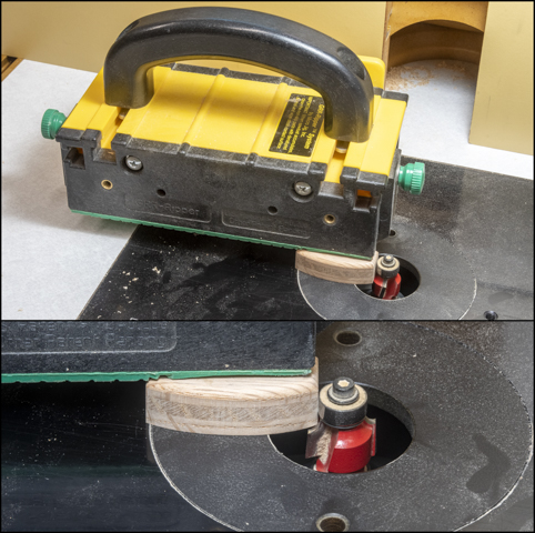
The first step is to route a notch in one end using the router table.  Here the width of the cut is controlled by the interchangeable bearing (red arrow) on the top of the bit.  There are different diameter bearings to go on this bit to make different width cuts.  Having a wider blank to work from makes it easier to control.  While not shown here I did use a push block when making the cut to keep my fingers away from the bit.

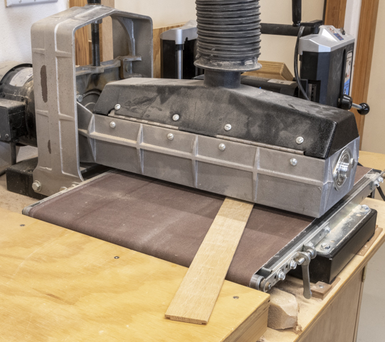
While the notches are cut the required depth the overall thickness is just a little too thick.  The blank is brought down to final thickness using the thickness sander.  With this tool I can take off a tiny bit at a time until the thickness is just right.  A plus is the surface ends up nice and smooth because with the last couple of passes 220 grit sandpaper is used.

Next is to rip the pieces to width.  That’s done on the table saw with the rip fence set at the desired width.  Here again having a wider than necessary blank makes it easier and safer to cut the narrow strips.  After the first piece is cut off the blank gets flipped end for end and the second piece gets cut using the same setup.  Both parts are then cut to final length with the chop saw.

Attaching the new spacers to the template is done using double faced carpet tape.  These pieces are not going to be under much stress so it’s plenty strong enough to hold them in place.  The top photo shows the spacer and tape ready to go while the bottom photo is a closer view. 

After both spacers are in place they are taken out of the template and clamped together overnight so the tape has time to make a good bond.  The middle photo is the finished spacer in place and the bottom photo is an edge view with the wood spacer attached to the aluminum rail.

Here is the setup for routing with all of the letters routed.  The small letters are done with a ¼” round nose bit.  The large letters are done with a slightly larger 3/16” round nose bit.  You can’t see the bit because the plunge part of the router is in the “up” position.

To make the letters stand out I gave them a couple of coats of paint.  If you wonder why the letters are painted from right to left it’s because I am left-handed and working that way gives me place to set my hand without having to worry about smearing the paint.  While I was careful about keeping the paint within the letters there was some places where it got a little untidy.  That’s easily cleaned up by making a couple of passes through the thickness sander loaded with 220 grit sandpaper.  It removes the paint leaving a clean crisp paint edge along with a nice smooth face.

While I probably won't use the template a lot now it does a nice job and gives good results.


Monday, December 12, 2022

L-Fence - #5 Wet-Sanding Lacquer, Sizing Carriage Bolts, Assembly & Jig Use

After letting the lacquer cure for a few days, the front of the fixed backer and the back of the L-Fence assembly gets wet sanded starting with an 8,000 grit pad and ending with a 12,000 grit pad.  When that’s done the masking tape is removed and the surfaces get waxed to make them as slippery as possible to make adjusting the jig easy.  The back of the fixed backer and the front of the L-fence assembly gets just the 8,000 grit sanding since I don’t need as slick and polished surfaces as the previous faces since these won’t be sliding against anything.  Once the wet sanding is done the handle gets screwed back onto face of the assembly.  The photo shows the gray 8,000 grit wet sanding pad.  It’s attached to an MDF block using the hook and loop system.

The carriage bolts that clamp the adjustable L-fence to the fixed backer ended up needing to be 2¾” long.  I can buy either 2½” or 3” long ones but not 2¾” ones.  Cutting them off is not much of a problem.  First, the bolt is securely attached to a block using a ¼”-20 die as a nut.  Second, is to wrap the end of the bolt in masking tape and mark the cut location.  I use masking tape so it’s easy to see where to make the cut and to give the blade something grab onto when starting the cut.  If there are a lot of pieces needed a jig saw with a metal cutting blade would be used.  However, here with only two to cut I use a hacksaw.  When the die gets removed it cleans up the threads that were damaged when cutting.  That’s followed by grinding the cut end smooth and last using a fine file to knock off any remaining sharp edges.

Reinstalling the “T” nuts in the fixed backer is next.  A socket and C-clamp are used to do that.  The socket is used because the “T” nut gets pressed in just below the plywood’s surface so something smaller than the outer diameter of the “T” nut is needed.  The other clamp is holding a piece of plywood in place to keep the C-clamp from marring the lacquer finish.

The last bit of work is to glue the carriage bolts in the knobs.  That can be done with either epoxy or super glue.  In this case I used a couple drops of super glue.  With that done the jig can be assembled and put to use.  Here it is attached and ready to go.

One big use of the fence is to replace the sacrificial fence when cutting tenons or making rabbits.  As I said in the first post the usual method is to clamp a scrap piece of plywood or in this case a piece of old countertop to the table saw rip fence and bury a part of the dado blade in it.  The problem with this method is the sacrificial fence gets chewed up as dados get cut and it has to be replaced.

For example, to make a 3/16” wide rabbit, ¼” deep using the L-fence a series of dado blades are stacked up on the table saw wider than 3/16” .  The table saw is then set for a ¼” deep cut.  Next, the L-fence is set so the bottom of the adjustable part clears the top of the dado stack to keep it from being cut.  Last, the saw’s rip fence is set so 3/16” of the dado stack is exposed.  The lower left drawing below shows that all done.  The top photo shows the jig on the saw with the setup complete and after the cut is made.  For clarity the table saw’s miter fence has been pulled back out of the way.  The bottom right photo is a close in view of the cut showing what the first tenon cut looks like.  In this example the dado stack at 5/8” wide is way bigger than needed but is does not matter since what’s under the L-fence is out in the open.  This is an advantage as it eliminates the time needed to add or subtract dado blades if there are several cuts of varying widths since you can stack the blades for the widest cut and use the L-fence to set the width.

Another use of the jig is to put a straight edge on a piece whose edge is bad or needs to be cut not parallel to an existing edge.  Examples include getting rid of irregular sap wood on an edge or cleaning up an edge when neither side has a good edge to work from or the piece is too small to use the jointer.  It could also be used if you wanted to align a new edge to the existing grain if it’s running at an angle or cut a taper.  This process starts by taking a known straight piece and using double face tape stick it just about 1/32” offset from the final cut.  The top photo shows a piece of 1½” thick walnut with a rough edge whose opposite edge is not straight either.  The bottom photo is a closer view of the left end.

Next is to raise the adjustable part of the L-fence so the face of the tapered edge is near the top of the straight edge piece that’s attached to the walnut.  The saw blade is raised enough to cut through the walnut but not so it cuts into the bottom of the L-fence.  That’s been done in the here.

The last step is to adjust the fence so the outside face of the blade is about 1/32” back of the edge of the L-fence as shown below.  This keeps the saw blade from cutting a notch in the straight reference piece.  The piece can now be cut using the straight edge that’s attached to the walnut as a guide against the L-fence.

After making the cut this is the result, a nice smooth straight edge.  In the bottom photo you can just see where the walnut is sticking out in front of the oak straight edge.  That’s due to the 1/32” offset.  This way I get to keep the uncut straight edge piece to use again.

Last is straight line pattern cutting.  Process here is to make a master pattern then double face tape it to a blank.  This assembly is then used to set clearance under the adjustable part of the L-fence and last move the table saw’s rip fence so the outside face is flush with the L-fence.  This is the same setup as used to rip a straight edge except for the 1/32” offset.  Here there is no offset and that’s so when the cut is made it’s perfectly flush with the pattern making an exact duplicate.  The photo below shows a sample plywood pattern set on a solid piece of cherry.  In use the L-fence rides along the pattern edge while the table saw blade cuts a perfect match to the master pattern.  In this case since the base of the pattern is set flush with the bottom of the blank three cuts are needed to make a matching piece.


Monday, December 5, 2022

L-Fence - #4 “T”-nut & Threaded Insert Installs – Spraying Lacquer

Two of the knob/bolt assemblies are used to clamp the adjustable L-Fence assembly to the fixed backer board.  Installing the T-nuts in the fixed backer board that the knob/bolt part gets screwed into is next.  The top drawing shows how all that fits together.  The location of the T-nuts gets marked by tracing the slot in the adjustable L-Fence assembly onto the fixed backer board.  That’s shown in the bottom photo along with a small pilot hole drilled through the piece centered on the slot to be used for the next steps.

Next the piece gets flipped over and the recess for the T-nut gets drilled as shown in the left photo.  It’s just about 1/64” deeper than the T-nut’s flange is thick so the flange is a tiny bit recessed.  With that done the piece is flipped back to the first side and a clearance hole centered on the pilot hole is drilled.

Last is to install the T-nut.  Because the flange is recessed a spacer whose diameter is smaller than the T-nut’s flange is needed.  In this case a 7/16” socket worked out fine.  The left photo shows the C-clamp used to press seat it and the right photo shows it installed.

Here is a close-up front and back view.  The left photo is the front where the knob/bolt will attach and the right one is the back or exit side.

Here is the jig with all the completed pieces in place.  It’s not done but now I can do some testing with how it sits here.  Some of the to-do includes attaching the laminated oak L part of the fence to the adjustable backer and the other two knob/bolts along with their threaded inserts plus a handle on the adjustable backer assembly.

First is to drill the holes for the knob/bolts and then install the threaded inserts they will get run into.  The top photo shows the pieces involved.  The red arrows point to the threaded inserts to be installed.  In the bottom photo the drill press is set to drill a guide hole through the end block and the adjustable backer.  This guide hole goes through where one of the screws was when the end block got glued to the adjustable backer.

With the guide hole drilled the adjustable backer is clamped to the fence straddling jig and the same bit used to drill a dimple through the guide hole into it.  The blue tape is my drilling depth marker.

Next is to take the fence straddling jig and using the same bit that drilled the guide hole center the jig under it as shown in the left photo.  In the right photo that bit has been swapped out with a larger one and a hold drilled that the threaded insert will get installed into. 

Before installing the threaded insert, I want to cut a little chamfer or bevel at the top of the hole to reduce possible splitting as the insert gets run in.  That’s been done with the bit shown in the left photo.  In the right photo a black arrow points to the insert which has been threaded onto the installation tool.  OK “installation tool” is a bit of a stretch as it’s actually a bolt with the head cut off along with a couple of jamb nuts added to lock the insert in place.  From here the insert gets installed by lowering the chuck and turning it by hand so the insert threads its way into the piece.  The center bottom photo shows the installed insert.  There is another insert at the other end and the same process is done with it.

Next a handle gets screwed to the adjustable backer assembly.  It’s made from a small piece of oak where the exposed edges get the same rounded edge treatment using the router as the knobs.

Next to last before final sanding is to glue the tongue on the laminated oak piece into the stopped groove in the adjustable backer.  Those two pieces are shown in the top drawing and clamped together in the in the bottom photo.  This photo just proves the old woodworking adage of, “You can never have too many clamps.”

Last is to run the adjustable backer assembly through the saw taking a skim cut off the laminated oak’s edge.  That’s to make sure the cut edge is dead parallel to the table saw’s rip fence.  Once that’s done all the pieces get sanded and any sharp edges get rounded.  I had debated on putting any type of finish on the jig but finally decided that because the sliding joint between the back of the adjustable backer and the front of the fixed backer needed to be as smooth as possible a lacquer finish would work best. 

With that decision made a little preparation needs to be done before actually starting to spray the finish on.  First, is to mask off the areas where plastic laminate had been applied since I don’t want any lacquer sprayed on them.  Here is what one of each of those edges looks like.

Second, is to remove the T-nuts so they don’t get lacquered.  Rather than screwing in a bolt and pounding them out a thumb screw and some spacers allows me to gradually pull the nut out minimizing chances of chipping the edges during removal.

The finish is going to be three coats of lacquer.  Here in the cans are the various items to be mixed together along with the mixing containers and safety equipment.  One note on the respirator is the replaceable pink filters are N100 for filtering plus being certified for removal of organic and acid vapors.

Since the handles are small, they get sprayed with the air brush.  Here I have just finished putting on a coat and used thinner to clean the air brush up.  The lacquer mix is in the bottle not on the airbrush.

The two larger pieces get sprayed using the HVLP (High Volume Low Pressure) gun.  This is a couple views of the setup for the movable backer.  It’s set on a lazy-susan to make it easy to spin around to spray all sides. 

The flat fixed backer gets sprayed using the same HVLP gun but not the lazy-susan.  Painter’s triangles are used instead to raise the piece off the carboard.  Once the pieces have three coats, they are set aside for several days for the lacquer to cure.

Next Up – Wet-Sanding Lacquer, Sizing Carriage Bolts, Assembly & Jig Use

Monday, November 28, 2022

L-Fence - #3 Plastic Laminate, Guide Blocks & Starting Knobs

In operation the “L” fence assembly slides up and down between a pair of end guide blocks.  To make the sliding operation smooth the ends of the adjustable backer and its mating edge on the guide blocks get faced with a smooth plastic laminate.  The drawing below has red arrows pointing to the faces that will get the laminate.

These laminate strips are made from a cutoff left over from a previous project.  Because the laminate is thin and brittle to reduce the chance of breakage when being cut a sandwich is made with a couple of sacrificial pieces above and below the laminate like this.

Once the rough blank is cut next is cutting the slightly oversize narrow strips that get glued to the ends of the pieces.  This is what the sandwich looks like with the top piece removed.  Here the first strip is used to support the left edge of the top sandwich piece so it does not rock when the cut is being made.

The just cut strips of laminate get glued to the plywood edges using contact cement.  The photos show how they are being clamped while the cement cures.  In the bottom photo the two end blocks are clamped face to face and you can see how the laminate is a little oversized.  It’s oversized because once the contact cement is applied to both surfaces and allowed to set when you put the laminate on the plywood it grabs instantly and no adjustment is possible.  Once cured the laminate will get trimmed to fit the plywood.

Trimming the laminate is done using the small router with a straight bit that has a guide bearing on the end guiding the laminate cut flush with the oak plywood.  Below the top photo shows the router, its bit and where just a short section has been trimmed flush.  The inset photo is a close-up view of the router bit. The bottom photo is after all the laminate has been cut flush with the oak.  Because the just cut laminate edge is sharp, I need to break the edge with some 220-grit sandpaper.

Drilling mounting holes for the screws is next.  That’s done on the drill press with a bit that cuts both the pilot hole for the for the screw along with a countersink for the head.  The insert photo is a closer look at the bit itself without the stop collar.

Once the holes are drilled, the guide blocks get attached to the backer board.  If you look closely, you can see where the blocks are a little long extending past the ends of the backer board.  That’s done so once they are glued and screwed in place, they can be trimmed to final length using the chop saw for a perfectly flush end.   I started by attaching the right one first.  After that the adjustable part of the jig gets set in place then the left block is brought up tight enough so the adjusting assembly can move easily but not loose enough to wobble.  The goal is to have the a fit where the piece moves easily but snug enough so the blocks keep the piece parallel to the bottom of the jig.

Next is to make four knobs shown in the drawing below.  Two are used to attach the “L” fence to the table saw’s rip fence straddling assembly and two are used with the adjustable part of the “L” fence.  I start by taking some thin pieces left over from resawing oak for other projects and gluing up three layers so the grain in the center piece is at 90 degrees to the face layers, just like plywood.  This will give the knobs some additional strength to resist splitting along the knob’s long dimension.  You can see the three layers in the left photo below.  The lower right photo shows how the piece will get cut into six knob blanks including the saw kerfs.

After cutting the blanks out a ¼” square hole (mortise) gets cut partway through the knob blank for the square part of the carriage bolt to fit in.  Below in the left photo you can see how the threads in the bolt transition into a square shoulder underneath the bolt’s head.  The right photo shows the mortising machine setup used to make the partial depth square hole with the mortise just started.

After the square mortise gets made a hole for the threaded part of the bolt is drilled through the blank.

Laying out the curved sides of the knob is next and to do that the pattern in bolted to the knob blank and it’s outline traced.  Below is a side and top view of what that looks like.

With the knob shape drawn on the top the curved edges get made using the large disk sander.  The bottom photo is a closer view where the closest edge is almost to the line but not quite.  The face up against the sander is just getting started.  I don’t completely finish one side before starting on the second side because as the piece gets sanded the wood heats up and can burn.  Working back and forth gives the sides a chance to cool off a little reducing the chance of burning the edge while sanding.

When that’s done it’s time to route a small radius on the top and bottom edges softening them.  In the bottom photo you can see where the top has been finished and the bottom is ready to go.  When the top and bottom routing is completed, the vertical edges will still be sharp.

Rounding those sharp edges is next and that’s done using three hand sanding blocks loaded with different grits of paper.  Last is some hand sanding using a small piece of 220 grit sandpaper to knock off the points where the horizontal and vertical rounded edges intersect plus do any blending as needed where the routed edges meet the flat surfaces.  The photo below shows each of the four steps needed to go from the mortised and drilled blank to a shaped knob.  These will get set aside for a while before the carriage bolts get installed.

Next Up – “T”-nut & Threaded Insert Installs – Finishing