Router Plane

Monday, June 27, 2022

Planer Sled - #3 Starting Sliding Blocks, Base Plates & Leveling Bars

With the sled base done next is to move on to the leveler assemblies.  Here is what the six of them look like set up on the sled base.

The first group of pieces to be worked on in the assembly are the 12 sliding blocks.  There are two kinds of these blocks.  Six of them have a T-nut set into the side which is shown in the inset and the other six do not, other than that they are identical.

The sliding blocks are made from oak as they will get the most use sliding along the sides of the sled.  In searching though my scrap box, I could not find big enough pieces so decided to glue up what I had to get what’s needed.  Once the necessary pieces are rough cut to size, they get glued and clamped together.  It doesn’t clearly show it here but there are four blanks made up of two pieces each.

While the glue cures the leveler assembly’s base plates get rough cut to size.  They are ¼” thick and could be made out of the MDF except almost all I had got used making the sled base.  I do have some leftover ¼” oak veneered MDF leftovers so used them.

When the glue cures, the slider block blanks are removed from the clamps so they can be cut down to their near final thickness and length.  Here they are setting on the table saw ready to start that work.  The sliding blocks are 3” long and these blanks are about a foot long each so three or four will get cut out of each blank. 

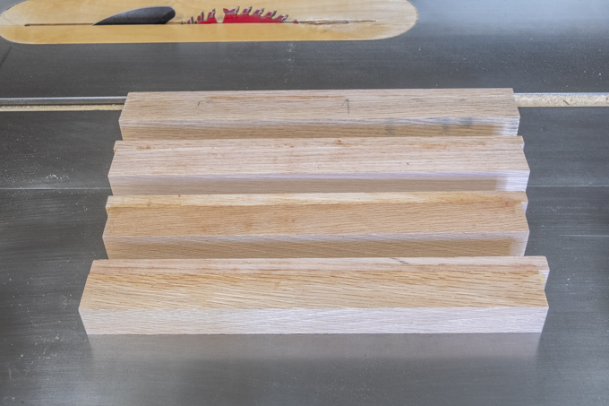
After making a clean cut on the ends they get cut to the correct width on the table saw and a little thick. They then get run through the thickness sander to remove any saw marks shown below in progress.  They are still slightly thick to allow for some final fitting later.

Next is to cut a small rabbit to fit under the lip of the top skin on the sled base.  That could be done on the table saw or the router.  In this case a router is used to make sure I get a flat bottom and a sharp inside corner.  The rabbit is cut while the blank is long so I don’t have to work on smaller 3” long parts.   This photo shows the setup on the router table along with the gripper used to keep my fingers away from the router bit.  Speaking of the router bit most of the time when cutting a rabbit, I use a straight bit and the fence.  However, in this case the bit has a bearing on the end that limits the cut to ¼” deep, which it what’s needed.

After the rabbit is cut the blanks get run though the thickness sander to fine tune the thickness.  When finished the top of the blank is just a tiny bit below the top.  This is so when the sled is used there is just a little clearance so the sliding block moves freely.  Once fitted the long blanks are cut to their final 3” length on the chop saw using a stop for consistency.  Since the base plate width is the same as the sliding block length they could now be cut to their final width.

Making the leveler bars is next.  They are 1½” tall, 1¼” thick and about 12” long.  I decided to make them out of a Douglas fir 2x4 left over from the Glider/Swing project.  The drawing below shows what they look like and where they will go in the leveler assembly.  The bottom photo is of the two 2x4 pieces that got so twisted and contorted as they dried that they were unusable for anything in the glider.  Due to the leveler bars relatively small size it seemed worth it to take a chance and see if one piece could be cut down, flattened and straightened out.  It was going to be either that or they are firewood. 

The end result is that after a lot of work with a hand plane to remove the twist and the table saw to get straight edges I ended up with flat and square oversize blanks.  Not trusting them to stay that way they were set aside to see if they were done doing an impression of a pretzel.  A week later they were still in good shape so they got cut to final width and thickness.  As their final length is the same as the base plate, they were all cut using the same stop block shown below on the chop saw for consistency.

Here in the top photo is the sled bottom along with the base plates, leveler bars and sliding blocks all cut to their final length, width and thickness.  They are not done as there is still quite a bit of work yet to do on them.  In the bottom photo on the left side the red arrow points to the test leveling assembly using the sliding block cutoffs along with an MDF base plate.  To its right is a partially assembled leveler using the actual sliding blocks and base plate.  To its right is the rest of the base plates, leveler bars and sliding blocks.

Before shaping the leveling bars, I hit the edges with some sandpaper to soften the sharp edge and reduce the chance of getting any splinters.  The 120-grit sanding block works well to do that. 

Drilling the bolt holes are next.  First, the top photo shows the setup for the 5/8” diameter Fostner bit used to drill a ¾” deep flat bottom hole.  A stop is set on the drill press to control the depth and a stop clamped on the right sets the left/right position of the bar.  Its front/back position is set with the fence.  The bottom photo shows the second setup for a smaller 5/16” though hole for the ¼” bolt.  The left/right stop and the front/back fence are in the same place so the through hole is centered on the larger previously drilled hole.

In case that all does not make sense here is a section through the leveling bar showing the drilled holes.  The smaller hole does not go through since it is in an area that will get cut away.  That comes next.

Next Up – Completing Leveling Bars & Starting Leveling Wheels

Monday, June 20, 2022

Planer Sled - #2 Completing the Sled

Adding the rungs in the ladder is next.  This drawing shows the rungs that will get added.

The photo on the left shows the second rung set just to the right of where it will go.  The ones on each end will get added last.  The right photo is a closer view and the vertical pencil line indicates where the left edge of the rung will go.  The two holes are for the temporary screws that will hold the rung in place providing clamping force until the glue dries.

After the glue is applied to the back of the rung it is set in place.  Temporary spacers are added at the top and bottom then a clamp is used to pull the rung down tight to the already glued on strip at the bottom.  Next two screws are run in from the back as shown in the right photo to pull the rung tight to the bottom skin.  Last, the clamps and spacers are removed and any squeezed out glue is cleaned up.  The center bottom photo is a close view of one of the screws.  The washers are to keep the screw from making a divot in the MDF since their underside is cone shaped.  If I had round head screws the right size the washers would not have been needed since they have a flat underneath side of the head.  Anyway, when the glue dries the screws get removed.

These front and back photos below show all the rungs glued in place.  Screws were not used on the end rungs since they could be clamped in place.  Once the glue dries the clamps and screws will be removed.

With the rungs glued in place and all the temporary screws removed that were holding them in place while the glue dried the last long strip can be glued on.  The top drawing shows the piece I am talking about and the bottom photo is of it glued and clamped in place.

After the glue cures the clamps are removed and the assembly is run through the thickness sander to bring the rungs and long strips to the same thickness.  All the surfaces and joints were really close with only a few places that were not right.  Not for sure why it may have been due to a slightly different thickness in the MDF pieces or maybe a difference in the glue joint thickness.  What I do know is the difference between the high and low point was less than 1/64”.

Cutting the top and gluing it on is next.  The size is easy it’s the ladder width plus ½”.  The extra ½” is for a ¼” lip on either side as shown in the top drawing.  The bottom photo shows everything setup and ready for the glue-up to start.  The clamping for this step is a little involved.  I can clamp the front edge just like when the long strips were glued on.  That’s done by using the gray clamps and the front edge of the bench to provide a flat clamping surface.  The far edge and the ladder rungs can’t be clamped that way as there is no edge to clamp to.  I got around that by taking a long caul and screwing it through the top and into the base assembly to provide the clamping force.  That caul is identified by the red arrow.  Each of the screws in the caul has a clearance hole just larger than the screw so they move freely.  That’s so as they are tightened all the force goes to pulling the top skin down tight to the long strips.  Also, remembering the splitting problem I had during the MDF testing a small pilot hole gets drilled in the ladder to prevent that when the screws get run in.  Not in the photo but a part of the glue-up is a series of short cauls that are used to apply pressure to the rungs.

One last step before applying the glue and putting everything together is to put a small chamfer on each of the pilot holes.  Often when a screw starts a little bit of material gets pulled up into a small lip.  That lip can keep the two pieces just slightly apart leaving a gap and possibly weak joint.  In this case it could also cause the top and bottom to not be exactly parallel.  The left photo shows the hand tool used to make the chamfer and the right is a close view of a chamfered pilot hole.

The actual glue-up and clamping went quicker than expected once all the cauls were made and a dry run done to make sure it all went together OK.  Doing the layout and making the cauls took some time but it’s worth it.  The photos show the top skin glued on with all the cauls and clamps in place.

After letting the sled set overnight the clamps were removed and the sled was run though the thickness sander to take out any irregularities.  The assembly was really flat and it only took a few very light passes to flatten both the top and bottom skins.  When I checked the thickness with a digital caliper there is less than 1/100” difference between the high and low points and I am happy with that.

Patching the holes left from the screws that held the cauls in place with plastic wood is next.  This is what the piece looked like before the surface was sanded.

Using a random orbital sander starting out with 220-grit paper and working to 400-grit on both top and bottom faces gives me a very smooth surface.  I want that on the bottom to reduce the friction between it and the platen on the planer.  That’s why the 400-grit paper was used, it is a very fine abrasive and gives a smooth surface.  Later on, the sled will get sprayed with lacquer then wet sanded a with 12,000 grit pad for a glass smooth finish and waxed to minimize friction.

Next Up – Starting Sliding Blocks, Base Plates & Leveling Bars

Monday, June 13, 2022

Planer Sled - #1 The Beginning & Starting the Base

For a long time, well actually always, whenever I have had a twisted board or one with a curve, I used a hand plane or more recently a power hand planer to remove the twist and flatten the face of the board.  The most common, easiest and fastest way to do those operations is to use a long bed jointer however, I don’t have one.  To get what I want which is one with an 8” wide helical head and a 6’ long bed like the one below runs about $2,600 and up.  That’s more than I want to spend which is why I am still using hand tools.  I do have a planer but a planer does not flatten twisted boards it just makes opposing faces parallel and thinner.  Using my thickness sander does the same thing so it won’t work to remove a twist from a board either.

A couple years ago, a friend sent me a link to a YouTube video that described how to make a sled that can be used with a jointer to truly flatten a twisted board up to four feet long.  I kept the link and put it on my to-do-someday list.  Well, after the work and aggravation required to flatten the boards for the just finished Glider/Swing fresh in my mind now seemed like the time to go ahead and build it.  As I almost always do the project started out by building a 3D model in SketchUp modifying the YouTube design to fit my planer.  The finished model is shown below.  It’s about four feet long and twelve inches wide.

To use the twisted board is set on the sled with a series of six leveling bars.  The bars are then adjusted so they are at an angle that matches the underside of the twisted board so it is fully supported and does not rock.  The drawings below illustrate the board set on the sled before any of the leveling bars (red arrow) are adjusted.  Once adjusted the sled and board get run through the planer flattening the top face of the board a little at a time.  Once it’s flat the board is removed from the sled, the flat face laid down on the planer bed then run through the planer multiple times to make that face flat and parallel to the first face.  It may not make a lot of sense for me to try explain it here but when it’s done, I will take a twisted board and go through the process to flatten it.

The sled starts with the base which is a torsion box using ¼” thick MDF for the top and bottom skins.  They are sandwiched over a ladder skeleton made from ¾” thick pieces of MDF.  An exploded drawing is shown below.

The base starts by cutting the bottom MDF skin to size on the tablesaw.  The skeleton is next which begins by ripping the ¾” MDF to the correct width strips then cutting them to length.  To make sure the lengths are the same a stop is set on the chop saw.  Shown below is the setup for cutting the short cross pieces or “rungs” within the ladder.

After laying out the spacing for the rungs on one of the long strips both of them are clamped together and the centerlines transferred to the second strip using a small square.

With the rungs location marked a test clamping is done to make sure all the pieces fit tight and the completed ladder is square.  Everything checked out with no problems.

Starting the glue-up is next.  Because the ladder assembly has to be accurately located, I scored a reference line on the bottom MDF skin using a measuring gauge with a blade rather than a pencil.  The result is shown in the bottom.  A nice fine line cut into the face of the MDF. 

Unfortunately, two problems occurred to me as I thought through the glue-up process.  First the line is so light that it’s going to be difficult to get the ladder right on it.  Second and more important there are 13 pieces that make up the torsion box and all of them except for the ladder rungs need to be really precisely located when glued in place or it’s going to cause problems later on in the build.  Thinking about trying to locate the pieces where they go when they are all slippery with glue at once sounded like a recipe for disaster. 

To reduce the number of pieces being glued at once I thought about preassembling the ladder’s parts so there would only be the ladder plus the two skins to worry about in the final glue-up.  Three pieces is a lot easier to work with than 13.  Just gluing up the ladder as in the clamping test is a possibility but I was concerned about a glued MDF joint being strong enough to hold together during the skins glue-up.  Reinforcing the joint with pocket hole screws would solve that problem so with some scrap MDF I made several test joints with different length screws and different depth pocket holes.  The bad news is they all failed.  When the screws are run in, they split the MDF.  You can see that in the photo below.  If the ladder was made with solid wood that would not have been a problem but I want to use MDF because of its dimensional stability.

What I finally decided to do is glue up the torsion box in stages.  The first step is to glue one of the long strips to the bottom skin.  One edge will go on the scribed line talked about earlier but the line is not the only thing used in setting the long strip in place.  Three spacers (red arrow) one at each end and one in the middle will also be used to locate the strip.  The photo below shows how the spacer gets clamped into the bottom MDF skin along with the clamp that holds the strip tight to the spacer.  This way I don’t have to worry about the strip slipping around while I tighten the clamps.

The gluing process once the spacers are in place is to spread glue on the strip, clamp it to the spacers to locate it then clamp a thick caul on top of the strips to spread the clamping pressure.  Here is what the glue-up looks like with all the clamps in place.

After letting the glue cure overnight all the clamps get removed and here is the result.

Next Up – Completing the Sled