Router Plane

Monday, September 27, 2021

Greene & Greene End Table - #19 Top Part 1, Drawer Slides & a Problem

While waiting on the drawer slides, I started work on the top.  It starts out with one of the original planks.  Here are the two halves, they give me plenty of material to make the top.  The bottom photo is of the right side of the two boards shown in the top photo.  In it you can see how well the grain is going to match up.

After cutting to rough length, I spent some time playing with the boards to get the best-looking grain flow across it.  This is the best arrangement that I could come up with and it looks good to me.  Total width needed is a bit less than 16”.  Right now, the stack is close to 18” wide so there is some room to bring the boards to equal width and trim out or at least reduce some things like the light-colored band at the first joint from the bottom.

Nothing has been done with these planks since they had been surfaced and the edges squared up.  When checking them after rough cutting to length all of them had a little bit of bow along their length as the photos below show.  It’s not a lot, about 1/16” along their 24” length.  A jointer would make quick work of flattening but I don’t have one.  The other alternative is to use a hand plane or the thickness sander.  Because the boards meet the following criteria, they can be flattened using the thickness sander which is both easier and faster than the plane.

  1. The pieces are thick enough to resist the downward pressure of the sander’s rollers so they remain bowed.  Too thin and the rollers flatten the board during its run through the sander which does nothing to remove the bow.
  2. They are short enough for almost the full length of the board to be in contact with the sander’s drive belt.  Since the sander’s platen plus infeed and outfeed tables only register the length of the board going across them the sander does not “see” the bow in a long board.  I once had a small jointer with about a 30” long bed and it was useless in trying to straighten edges of long boards for gluing together because of that.


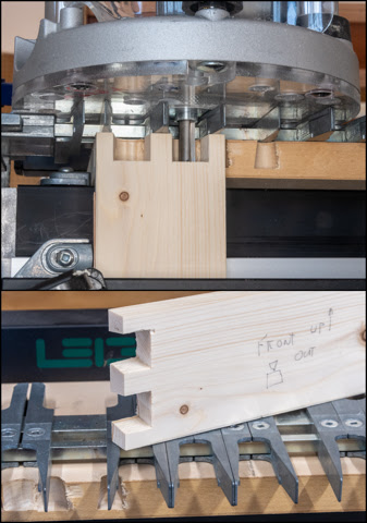
The process to flatten the boards begins with selecting the crown side and crosshatching it as the first side to flatten.  The crown goes up so the board’s end corners are the contact points on the sander’s base with the drum sanding of the top.  If the crown went down the board would pivot following the curve as it passes through the sander.  The top photo shows the result after a couple of passes through the sander loaded with 36 grit paper.  The center is flat since the crosshatching is gone but still visible at the ends.  The bottom photo is a closer look.  Once all the crosshatching is gone the piece is flipped and the flattening steps repeated.

For the top there are also a couple of end pieces called breadboards.  I don’t really know why but it may be because they helped keep bread boards flat???  There are a lot of ways to attach them to the top.  Right now, the plan is to use a long tenon on the center part of the top with matching grooves in the breadboards along with wood dowels installed from the bottom.  A set of ebonized inlaid pieces are added to strengthen the joint. 

The breadboards come from the remaining length of one of the boards used to make the top.

After the four pieces that make up the center section of the top set for a couple of days, I checked to make sure they are still straight and flat.  They were so after a skim cut of the edges, I started gluing them together.  Here is a photo of one of the initial two board glue-ups.

The next day after removing the clamps the surfaces were crosshatched then run though the thickness sander to remove any little variances in the surface.  Below are the two-initial glue-ups flattened.

The previous evening the drawer slides arrived so today I am going to install them.  They are two-piece, side mounted, ball bearing, full extension ones with a 100-pound limit.  The weight limit is overkill but I like this kind of slide since they work so easy and will last practically forever.  The photo below shows the table on its left side with the front at the right.  The cabinet mounted half of the slide is in place.  For spacing a couple of shims are used so it’s easy to get both slides mounted in the same location.  One mounting screw on it right has already been installed with one more on the left to go.  The hole is drilled with a self-centering bit assembly mounted in the drill.  In use it will center the hole in the slot.

Here is the left side of the drawer with the half of the slide that gets attached to it.  It’s located by setting the drawer in place then marking the center of the cabinet mounted slide half on the drawer.  The center of the drawer half of the slide is centered on that line and screwed in place.  The vertical slots are used to make any fine height adjustments later on.

Below is the drawer mounted in place.  It still needs the false front with matching veneer but otherwise is built.  It’s a little hard to tell from the photo but the drawer is recessed into the table so when the false front gets added its face will align with the small panels on either side of the drawer. 

The next step is to rip a piece of oak to ½” thick then cut it to rough width and length.  That’s all been done before so need to go through it again.  However, when getting ready to glue the leopardwood veneer on I ran into a problem.  Earlier when making the veneered panels a leopardwood/cedar one was made for the drawer front and that was an error.  I should have left the veneer piece for the drawer front alone and not glued it to the cedar backing.  Now I have a grain matched panel specifically for the drawer front since it’s cut from the same piece as the side panels but with cedar backing that I don’t need.  That’s a problem I will have to sleep on.

Next Up – Drawer False Front & Plugs Part 1

Monday, September 20, 2021

Greene & Greene End Table - #18 Drawer Part 2

With the test dovetail joint done I marked up the oak drawer parts with all the information needed in preparation of making the actual drawer.  Cutting them follows the same process as the test piece so no need to go through that.  One item to note is that all of the pieces are longer than needed.  That’s insurance in case I make a mistake when cutting the joint there will be enough material to cut off the problem and redo the joint routing.  The only exception to having extra material is the last joint.  It’s the front’s second joint as the front needs to be cut to length so the right end can be cut.  Fortunately, no problems occurred during the routing of that joint.

Now that both the front corner dovetail joints are done cutting a groove for the drawer’s bottom is next.  The groove is centered on the bottom tail.  In the photo below you can see what the groove looks like along with the dado blades setup for making it.

Next is to cut the front and other side’s groove.  They are done with the same setup so the grooves align with each other.  This photo shows the right side and the drawer front assembled.

This outside view shows the same joint.  The drawer front is on the left and the right side is on the right.  One drawback of cutting the grooves the full length is they show up on the front of the drawer.  In this case it’s not going to be a problem as there will be a decorative false front applied on the drawer’s front to cover the gap on the side where the full extension metal slides will be mounted.  More on their installation later.  If I didn’t want the groove to show a stopped groove could have been cut with a router or a plug could have been installed to hide it.  I may add the plug just because later on.

After a little math the overall length of the sides is found then cut on the chop saw.  A stop is used to make both are cut at the same length.

Setting up the table saw to cut the dados in the sides for the back is next. The top drawing shows the dados circled in red that I am talking about.  The bottom photo shows the dado stack used.  Like most of the other stacks it consists of the two outside blades and interior chippers.  In this case two black 1/8” thick ones.  There is also one more spacer.  The blue disk the with .004 written on it is a four thousandths inch thick shim.  When I sized the drawer frame parts they ended up being four thousandths inch over ½” thick.  That was not a problem in making the dovetail joints or any other part of the drawer except when it came to fit the back.  My dado set has a whole set of shims for just this occasion and all I had to do was pull the right one out and add it to the stack.  In use the stack gives a .504” inch wide dado, just what I need.

This is the setup on the table saw with one completed dado on the fence.  Cutting the back to length and width finished out the drawer perimeter pieces. 

Last is cutting the bottom which is ¼” thick oak veneered MDF.  The drawer is not too big so it’s plenty strong.  I had an oversize piece that just fit the bill except one edge had been damaged and another one had been splintered plus none of the corners were square.  In a smaller piece I would have used the chop saw to give myself a 90-degree corner to work off of but the piece is too big to do that.  There are a few solutions but in this case the start is to cut off the damaged edges and find the corner closest to being square.  It was pretty close at about 1/16” off over 17”.  Using a small block plane, the edge is worked down to square.  From there the piece is cut square and to the appropriate size.

Here are all the drawer parts ready for the first glue-up. 

For now, only the dovetails get glued.  You can apply glue to all the mating surfaces but that generally leaves a pretty good mess of excess glue to clean up.  To minimize the mess the first thing to think about is how the joint goes together.  The red arrow on the part on the left (front) shows the direction that part goes when the two pieces are put together.  With that in mind to minimize the glue squeeze-out the glue goes on the other part on the yellow highlighted areas plus the two hidden surfaces on the underneath side of the tails.  Now when the front part on the left slides into the one on the right (side) any excess glue will be pushed to the outside face where it’s a lot easier to clean up than on the inside corner or in the groove for the bottom.

Once the dovetail joints are assembled four clamps are added, any minor excess glue is removed and the drawer is set aside for the glue to cure.

After the glue cures locations for screws holding the back on are marked and a pilot hole drilled through the side into the back.  That’s followed by removing the bottom and back then drilling out the pilot hole in the side so the screw can be countersunk.  Here is the drill press setup for that.  Later, the hole will get plugged hiding the screw. 

The bottom can then be reinstalled along with the back and the screws holding the back in place run in as in the top photo.  The bottom photo shows the three screws that secure the bottom to the back.


Sanding of the outside of the drawer comes next making sure the proud dovetail ends are brought down flush.  This is what the front left dovetail corner looks like finish sanded.

Here is what the looks like assembled.  The inside still has to be sanded as well as all the sharp edges eased.  Later plugs for the back screw holes will be installed too.  For now, it’s going to be set aside while I wait for the full extension drawer slides to be delivered.  I needed 12” long ones that are not available locally so had to order them.

Next Up – Top Part 1, Drawer Slides & a Problem

Monday, September 13, 2021

Greene & Greene End Table - #17 Drawer Part 1

Making the drawer is next and here I decided to make a change in the plans.  Originally the drawer was to have ridden on the guides I had just finished.  That version is shown in the drawing below.

However, in thinking about the amount of use it would get I changed the wooden guides to full extension steel guides.  The revised drawing is below and the only change is the drawer is an inch narrower to allow for the slides.  Other than the dovetail joint where the front and the sides come together the construction is pretty straightforward.  I am using dovetails at the front for a couple of reasons.  Since the front to side joint gets the most stress when the drawer is opened and closed a strong joint is needed.  Because of the way a dovetail joint is shaped it has a mechanical strength and does not rely on glue alone to hold it together.  The other reason is I like the way they look.  Since the back to side joint is not really stressed it will be a simple dado.

Selecting the wood is next.  The selection got narrowed down to three choices.  In the photo below the left two pieces are red oak and the right one is maple.  The maple got eliminated as this is a pretty good size board and I wanted to save it for something larger than a single drawer.  That left the two oak pieces.  I decided on the far-left piece since it is the lighter of the two and I wanted the drawer to be light in color.

The process starts by cutting the front, back and sides to rough length and width.  From there the pieces are run through the thickness sander to remove planer scallops, flatten and get a smooth working face.  Here one of the pieces has just come out of the sander ready for the next step.

Since the drawer frame is ½” thick and the oak is 13/16” thick it has to be brought down.  There are three possible ways to do that.  Running it through the planer or sander converts over ¼” of the boards to chips and in my opinion is just a waste.  I prefer to cut close to final thickness and save the thinner pieces for something else.  Here is the bandsaw setup used to rip the oak down to about 3/32” oversize.

After ripping it's back to the thickness sander now loaded with 36 grit paper.  This photo shows the bandsawn faces ready to be smoothed out in the sander.  A couple of passes with the 36 grit gets rid of 90% of the roughness. 

Finer grits are used to quickly smooth the pieces ending up with ½” thick blanks.  The ½” is not absolutely critical but having it accurate will make things simpler when sizing the length and width of the drawer.  As you can see there are six pieces of wood here.  Four oak pieces for the drawer frame plus two others the same thicknessbut are pine.  They will be used as test subjects when I do machine setups.  Last, the pieces are ripped to width.  Cutting to length comes a bit later after the first set of dovetails are made.

This is the jig I use to cut dovetails.  The thing that sold me on this jig is the spacing of the dovetails is variable.  They can be adjusted for just about any height drawer and their spacing can vary within the joint’s width.  On the left set vertically into the jig is the test drawer side. 

Using this jig produces really good results but it does take some time to set up and adjust to make good fitting tight joints.  I will hit the high points of the setup to give an idea of how it operates.  Because of the close tolerances when making the joint the router bits need to be dead center in the router's bushing.  The bushing is centered using a steel rod which is ¼” on one end and ½” on the other with a taper where the two meet.  The router base is loosened the rod mounted in the router collet and the base adjusted so the taper is snug against the brass bushing centering it in line with the router shaft.  The base is tightened down and the rod removed.  The left photo shows the whole router and the right one shows a close-up of the centering rod.

The correct sized dovetail bit is installed in the router followed by setting the router on the jig between its guide fingers.  The depth of cut is adjusted to just remove a line that’s the thickness of the drawer frame plus just a smidge, here that’s a fat ½”.

Here the router is set on the jig, the test side piece clamped in place with everything ready to cut the dovetail tails.

This is a close-up of after the tails have been cut and the test side removed from the jig to show how the tails look.  Their depth is checked to see that they are just a little deep and adjusted as necessary.  That little extra allows for the tails to be sanded flush with the front since it’s easier to sand the tails down to the front versus sanding the whole front down to the tails.

Making the pins starts the same as the tails by centering the base on the router and installing the appropriate bit.  In my case it’s in a second router so if adjustments need to be made, I can make them independent of each other without having to go through the whole setup process.  Below is the setup for the second cut or the pins.

This is underside view after the cut is made.  There are a couple of differences from the tails.  The bit is straight cut and the jig guiding the router has been rotated 180 degrees to a different shape.  That shows up a little better in the bottom photo.

After a few tiny adjustments to the jig position and cutter depth here is what the finished assembled joint looks like.  A nice snug fit with the board ends just barely long.  The time required to do the setup to make just two joints for the front of the drawer is not a really efficient use of time.  If I were doing a whole set of drawers then that would be a different story as once it is set up the actual cutting goes really quick.  However, I made the joints with the jig because the results are better than if I hand cut them and I have plenty of time to work on the project.

Next Up – Drawer Part 2

Monday, September 6, 2021

Greene & Greene End Table - #16 Drawer Divider/Guides Part 2 & Shelf Supports

Installing the divider/guide assembly is next.  Once it is flush with the spindle in the front and square to the front rails clamps are added to make sure it does not move while the front pocket screws get run in.  That’s when this photo was taken.  One last check is done to make sure it is still square with the front rails and the back screws get run in.  The same process is done with the other side divider/guide assembly.

Because the space between the divider/guide assembly and the side rail is less than 1½” there is no way I can get in there to do any staining or lacquering.   So, after both are installed, they are removed and stained.  That’s followed by giving them three coats of lacquer along with the surfaces in the 1½” gap between the divider/guide assembly and the side rail.  This is what the divider/guides look like ready to go back in the base.  I will wait a few days for the lacquer to harden before installing.

I am skipping ahead to after the divider/guides had cured for a few days and are ready to install.  However, before installing they get wet sanded with a 3,800-grit pad to remove any little dust nibs.  They are then slid into place, the screws run in and they are done.

While waiting for the lacquer to harden on the divider/guides I started on the cross supports for the bottom shelf.  The top drawing shows what they look like and the bottom shows where they go.  As you can see, they are black as an accent to the oak.

Black wood is not common.  Now while I do have some Ebony that is absolutely black with no streaks but at well over a hundred dollars a board foot it’s not going to be used here.  In other similar instances I have used “ebonized” cherry or walnut.  Oak does not stand in well for ebony as its grain is way too open and pronounced.  Good ebony has almost no visible grain which is why a closed grain wood like cherry or walnut is used.  Here I am going to use walnut as I have a piece the supports could be made from with very little waste.

Once the supports are cut to final length, width and thickness a recessed hole and slots need to be made so the shelf can be attached for reasons covers in Post #12 Routing Edges & Slotting Rails.  In short, the slots allow the shelf to move when its width changes due to humidity fluctuations.  The recess is so the screw head is hidden from view.  The process starts by making the recess.  First, the drill press fence is adjusted so the drill is centered on the support piece.  Second, a stop block is clamped to the fence for repeatable accuracy and last a depth stop is set so the holes are all drilled the same depth.  The top photo shows the setup after both ends of the recessed slot have been cut shown is the setup for the center.  The bottom photo is a closeup.

On the set of slots for mounting the top I drilled end and center through holes then using a chisel, Dremel tool and file finished the slots.  Here I tried something different that worked a lot better.  After drilling the end and center through holes I continued drilling more holes moving the support piece sideways a little at a time until I had an almost completed slot as the photo below shows.  A little touch up work with a file and I was done.

The ends of the supports get a small 45-degree bevel.  Using a scrap piece of oak, I tried 1/16” (left) and 3/32” (right) wide bevels.  To my eye the larger 3/32” bevel looked the best.

To make the bevels the dial calipers are set at 3/32” and a line marked on all four sides of the support.  A 12” disk sander is used along with a miter fence set at 45 degrees to make the bevels.

Because the disk sander has 80-grit paper on it the bevels are not very smooth.  They are smoothed out using 120 then 220 grit hook and loop sanding disks.  The 80-grit paper on the 12” disk sander grabs the hook and loop firmly enough that the bevels can be smoothed out by sliding the miter fence back and forth in the miter slot to move the piece across the finer grit disk.  You do NOT want to turn the 12” disk sander on while doing this.

Here is what the supports look like set into place.  The slotted and center holes are clearly visible.  After they get ebonized, they will be screwed in from the underside of the front and back rails. 

Last step before ebonizing is to sand all the surface with 400 grit paper so I have a very smooth scratch free surface to work with.  In the past my ebonizing has been accomplished a variety of ways with varying degrees of success.  So far, the best-looking result has been to use Super Black India Ink.  It gives a dense black, soaks into the wood and is light stable so it should not fade over time.  Also, the solvent is denatured alcohol so when applying it does not raise the grain.  The photo below has one support done and the other ready to do.

The alcohol evaporates quickly with the low humidity here so they could have been installed after a short drying time but it seemed like a good place to quit for the day.  The next day I screwed them in place using screws that fit in the recess.  

Next Up – Drawer Part 1