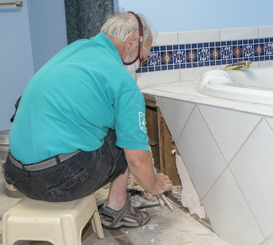
Router Plane

Monday, August 29, 2022

Master Bath Remodeling - #3 Concrete, Drywall, Electrical & Starting Tiling

Here the in the left photo you can see how the rerouted water line and the wall cavity gets insulated. The right photo shows the pit where the capped bath drain piping is all filled with compacted sand ready for the concrete pour.  One step not shown was to remove a raised area around the pit so it’s in the same plane as the rest of the floor.  My guess is the original forming for the pit was a bit high ending up with a little ramp all around it.  This ramp has to be removed so the tile will lay flat.  The same an old school combination of a hammer and chisel removal method was used here to minimize dust.

The pit took very nearly a whole bag of pre-mixed concrete to fill it.  Since it’s a lot easier to bring a patch up level with a surface versus removing the hardened concrete a 1/8” thick spacer is nailed to the bottom of the screed (red arrow) in the left photo.  Later on, a thin layer of fine patching material will be used to bring everything level.

There are three items in this photo.  First, on the left is where the original access door from the outside to under the tub is.  In that space new insulation has been added.  The next time we need to do some stucco repair on the house’s exterior the door and frame will get removed and patched.  Second, having laid out the tile spacing on the floor the outlet gets set so the joint between two tiles is pretty much centered on it.  Notching two tiles to fit around the outlet is a lot easier than cutting a hole in the center of a single tile.  Third at the far right near the bottom there are several pieces of masking tape wrapped around the pocket door framing.  That’s because when removing the tub framing that piece split.  It was a clean split so some glue, clamps and tape held it in place until the glue dried repairing the problem.

Hanging drywall as a backer for the wall tile is next.  If this were a wet area then a waterproof cement board would have been used.  The top photo shows it hung with the taping and filling around the screws in progress.  Since this is going to get tile, it does not have to be perfect.  The bottom photo shows after the wall got a coat of primer.  That’s used to prevent the paper surface of the drywall from sucking the moisture out of the thinset too fast which would weaken the bond between the drywall and the tile.

Next is to add the thin layer of patching material to fill in the pit and level the surrounding areas.  There were some places where the concrete was chipped so I went ahead and filled them too since the patching material was already mixed up.

The last bit of work to do before starting the tiling is to check the edges of the existing tile on both the floor and the wall to make sure I had clean edges to work with.  Here in the top photo, you can see where the original thinset had oozed out beyond the edge of the existing tile.  The bottom photo shows where it has been very gently removed using the cold chisel shown.  This was very careful work as I sure didn’t want to crack one of the exiting tiles.

At last, the actual tiling can begin.  It starts with the transition strip between the existing tile and the new tile as shown in the bottom photo.  This strip is made of alternating new tiles and cut pieces from the existing original tiles.  The front to back dimension is set so it matches the width of the existing bullnose edge tiles shown in the top left photo (red arrow).  That edge treatment will continue down the wall until it meets the floor using the salvaged bullnose tile.  The length of the individual tiles in the floor transition tile strip was calculated so all of them including the end pieces are the same size.  Well, almost – the end tiles are ¼” longer to take into account the thickness of the bullnose tile that will set on them.  End result is all the tiles have the same exposure.  The top right photo is me cutting the tiles using by brother-in-law’s tile saw he so kindly lent me.
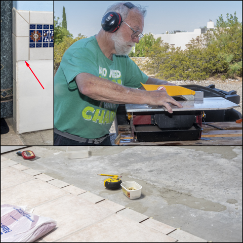
Laying the tiles can now start.  Thinset cement used to bond the tiles to the concrete is mixed per the package instructions.  After it sets for 10-15 minutes to make sure all the particles are well hydrated it is remixed and if needed adjusted by adding water or the thinset mix to get the proper thickness.  Applying the thinset to the concrete is done with a ¼” by ¼” notched trowel shown in the top photo.   The tiles are then pressed into place and wiggled around to make sure good contact is achieved.  Last, a rubber mallet is used to firmly set them.  I use plastic spacers to control the grout line width so they are consistent.  In the bottom photo the transition strip is set except for the end pieces and the center part of the floor field is laid.  The twelve tiles shown are the only full-size tiles I will be putting down.  Every other tile has one or two edges cut.  This is necessary because I want the tile pattern to be centered on the floor with the wall tile joints lined up with the floor tile joints.  Matching the grout lines off the old tile is not possible since the new and old tile are different sizes.

Cutting the full tiles to size is done by scoring and breaking them using this tile cutter.  I have had mixed luck scoring and cracking tiles depending on the tile type but these worked really well.  The last major tile job I did was 20” square porcelain tiles that were thicker and more difficult to get a good cut on. 

Here the top photo shows the floor with all the floor tiles set in place.  They still have to be grouted but that will be done after the wall tile is set in place.  The bottom photo is of setting the wall tile.  I used a slightly different method for them.  First, a thin layer of thinset is applied to the drywall with a 6” putty knife.  This thin layer guarantees a good bond between the tile and the drywall.  Second, the ¼” by ¼” notched trowel is used to apply the thinset to the back of the tile followed by setting it in place using the same process as with the floor.

Next Up – Completing Floor, Wall & Baseboard Tile

Monday, August 22, 2022

Master Bath Remodeling #2 – Finishing Demolition, Plumbing Work & A Problem

With a little more of the tub support framing removed I can get a clearer view of what needs to be done with the plumbing.  First, is to cut the drain line riser off a few inches below the top of the concrete slab as shown in the top photo.  Also shown in the top photo is the primer and glue that will be used to glue the cap on.  The bottom photo shows the drain riser cut down some more with the cap glued on.  I have also started to fill the pit with compacted sand so later it can be filled with concrete.

Next is to remove the copper lines feeding the tub and cap them.  Here a small tube cutter is being used to cut the copper pipe after turning the water off.  These are just rough cuts.  Once I get everything out of the way final cuts will be made after measuring to make sure the capped pipe will be hidden within the wall cavity.  The blue material behind the water lines is a plastic material that is a part of the shower waterproofing.  It’s going to make soldering the caps on interesting since I don’t want to melt it or worse yet start it on fire.  When cut most of the water drained out of the lines but since this is the low point of the system it kept dripping and didn’t get really dry which I need when soldering the caps on.  To get around this I used compressed air to blow most of the water out of the line through hot and cold open sink faucets. 

To prevent melting the plastic or starting it on fire when soldering some extra precautions are taken.  First, one of the old tiles gets wrapped with a wet towel and set between the water supply lines and the plastic.  Second, when heating the pipe and fitting for soldering the flame from the torch was never pointed directly at the wall.  It’s always at an angle and pointed away from the wall if possible.  With these precautions the tile never even got warm.

Here are the hot and cold-water supply lines capped with the water back on.  The pit has also been filled up with compacted sand and is almost ready for the concrete to be poured.

More demolition progress with some of the tile removed along with the framing and cement board the tile was set on.  The tile and framing need to be gently removed where it is adjacent to the existing tile that is to remain.  I don’t want to bang away and potentially crack the grout or worse yet a tile.  Fortunately, the tile setting was not done very well and the tiles were not solidly affixed to the cement board.  They came off easily and did not chip the wall tile when removed.

The demolition continues until all the unneeded framing, tile, plumbing and the like are removed.  Here in the top photo, you can see the existing electrical outlet the tub’s pump was plugged into.  It will get mounted to the wall once the tile layout is finalized because I want it centered on a joint and not in the center of a tile.  In the bottom photo the red arrow points to a ridge where the mortar base for the tub oozed out under its framing and left a ridge stuck to the floor.  This has to be removed so the tile will lay flat.  After trying different removal methods what worked was an old school combination of a hammer and chisel.  Grinding it off would have probably been faster but would have created way too much dust.

Moving back to the ¾” water line for the hose bib that has to be re-routed with all the extra tub framing removed the top photo shows what the corner looked like.  The red arrow in the bottom photo shows where I had to notch out a couple of studs to make space for the pipe’s re-routing.  Because the space is pretty confined and I am working around the existing water line there was not enough room to get the power saw in there.  As a workaround a series of almost touching holes were drilled then knocked out using a hammer and chisel.  The bit at the top right is the one used and if you look at the tip it has a lead screw which pulls the bit through the wood making it easier to drill the holes.

Once the notches were cut so the pipe could be rerouted the water to the house gets shut off.  The plumbing here is a little different than what I am use to in that the domestic water has a shutoff at the water softener after the main shutoff.  In practice this means that when I was working on the tub hot and cold-water lines the water could be shut off at the softener while the hose bibs remained live.  However, now since I am working on the hose bib line the main shutoff had to be used.  Once the water had been shutoff at the main 1½” gate valve the curved pipe could be cut out and rerouted.  This consists of a couple new short sections, a 90-degree elbow and two unions to tie it all together.  The same method of protecting the shower waterproofing and wood structure with a tile and wet towel is used here.  One addition is a wet cloth wrapped around the copper pipe near the elbow for additional protection for the stud.

Here is what the finished rerouting looks like.  The copper line against the outside wall will get insulated with pipe insulation like the pipe on the right side of the top photo.  The empty space will also get insulated with a fiberglass batt.

Unfortunately, when I went back to turn the water on at the main shutoff its shaft twisted off inside the valve in its closed position.  This meant the water could not be turned back on to the house.  The top photo shows the valve and the pipe section that I cut out after digging the supply line up.  Fixing this requires two people each using both their hands to glue two unions (red arrows) in at the same time.  Since there is only one of me, I had to call in a plumber for help.  Fortunately, they came out the next day and by that evening we had water to the house again.  The bottom photo shows the new valve and the unions.  Once the water was back on, I checked for leaks and found none which is always good.  My guess is this will be the most expensive item of the bath remodeling.

Next Up – Concrete, Drywall, Electrical & Starting Tiling

Monday, August 15, 2022

Master Bath Remodeling - #1 Getting Started & Demolition Part 1

This series of posts is on a different type of project than the usual subject matter.  Here I am going to go through a “simple” remodeling project consisting of removing a huge garden tub in the master bath.  We have long wanted to remove it and recover the space for usable purposes.  It’s about 7’ long 42” wide and 18” deep.  Filled half full it holds about 125 gallons of water and would completely drain our hot water heater.  It does have a whirlpool motor but no way to keep the water at temperature and is uninsulated.  In the 12 years we have lived here it’s only use has been to rinse various things.  Before we bought the house, we asked the former owner if he had used it much and he said only once.  Here is what the tub and its space look like.  My wife did run some water in it once and when she started the whirlpool pump it blew out spiders and all sorts of stuff.  That was enough for her.

Before, getting started on the demolition I wanted to see what potential surprises might be hidden.  Fortunately, there was a small 16” square access door on the outside of the house so I could partially see what was under the tub.  After carefully checking for scorpions, black widow spiders and other things I stuck my head inside to look around.  However, what worked the best was to stick my camera inside and take some photos.  That gave me a record and an easy way to review the situation.  After a careful review there was a lot of good news.  I had a full concrete slab under the tub just like the rest of the house in lieu of exposed grade, the electrical supply was an unsecured outlet box and the water supply was in the common wall with the shower which is going to remain.  So far, no deal breakers.  Here are the photos.

Because the house was built in 1997, we knew the chance of finding matching tile was going to be a stretch and sure enough nothing matched.  That left us with two options.  First is to use wood flooring like we have in the bedroom.  Since I replaced the original carpet with wood a few years ago it is still available.  Second, is to find as close a tile match as possible and work to integrate it in the area.  Deciding that wood flooring in a bath is probably not the best idea we went looking for a compatible tile.  We did finally locate a close match after going to all the tile stores in the area.  Based on that here’s the third-generation rendering approximating our plans.  The original wall tile from the tub deck up will remain and the new tile will go from there down the wall and onto the floor.  An alternating dentil strip made up from some of the few original tiles and the new tiles will make the transition.  There are a couple of assumptions made for this plan.  First, is that I can demolish the tub and remove the tub deck tile without damaging the existing wall tile.  Second, is to salvage the existing bullnose tile along the front edge of tub’s deck so it can be reused.  Below is the rendering and a drawing of the bullnose tile.  As this is only a rendering the actual tile, we found is closer to the existing than shown.

With the exploration work done it’s time to start on the demolition.  It starts by removing the face of the tub surround so I can see what was hidden when looking in from the access door.  That’s done by breaking the tile and gently pulling it off.  I had to be careful not to damage or chip the floor tile since they are to remain.  So far, no real surprises at what’s behind the tile or in removing the tile.

Next is to very carefully try and remove the bullnose tile.  That’s done by using a reciprocating saw that instead of having a blade in it has a carbide grout removal rake.  To keep the dust down my HEPA shop vac is used to capture the dust.  Once the grout is removed a thin putty knife is used to gradually cut the thinset holding the tiles in place.  There are six full and two short tiles of which one of them was cracked.  I need four full pieces to be reinstalled later.  The first short piece did not go well as I cracked it but all the full-length tiles came off in one piece although most have a lot of thinset stuck to the back that will need to be removed.  Here I am sawing the grout out with dust mask and safety glasses on.

By being careful all the face tile adjacent to the floor tile got removed without any damage to the floor tile.  It did make a pretty good mess though.  Behind the removed tile face you can see some of the plumbing that will need to be removed.

With the bullnose tile salvaged and the face tile removed next is to take out the tub.  It’s way too big for me to remove in one piece so using a variety of tools but mostly a framing hammer the tub got taken out piece by piece.  Here are the demo tools, a progress photo and the demolished tub ready to be hauled away.

With the tub out of the way the slab it sat on is next to be removed.  It ended up not being a concrete slab but I think one made out of mortar.  In any case it was pretty easy to break into pieces small enough I could easily handle and remove.

Once the tub along with the slab was removed, I could get a good look at the plumbing work that is going to be needed.  As suspected from looking through the access door the hot and cold-water supply lines are within the shower common wall so that’s a good thing and will make capping the lines feeding the tub relatively straightforward.  The tub drain is in the pit in the center so cutting and capping it should be easy.  However, the ¾” copper water line on the right (red arrow) that feeds the hose bib mounted on the outside wall used for watering the back patio plants is a problem.  The plumber who did the original work used Type K flexible copper to feed the hose bib and it is not run within the wall but arcs across the open area under the tub.  This means it has to be rerouted to run within the walls.

Next Up – Finishing Demolition, Plumbing Work & A Problem

Monday, August 1, 2022

Planer Sled - #8 Final Assembly & How to Use

Before putting the sliding assemblies together, a stop gets added to the leveling bar on the first and last assemblies.  The stop locks the piece to be surfaced in place so it does not slip and are replaceable if they get damaged in use.

Assembly consists of feeding the bolt through the hole in the leveling bar, threading it into the wheel then running the bolt into the threaded hole in the sliding base until the head is just about ¼” above the bottom of the leveling bar.  The whole assembly is then flipped over and a drop of Loc-Tight is put in the bolt hole from the bottom.  The bolt is then run in until it’s level with the top of the leveling bar.  As it’s run the rest of the way in the Loc-Tight gets spread on the last ¼” of threads locking them in place.  Here is the completed assembly.

After putting all the assemblies onto the sled base it’s time to do a test run of the sled.  For that I took one of the unusable twisted and bowed 2x4’s from the just completed Glider/Swing cut it in half and set it on the work bench.  To get an idea of just how bad the twist is a couple of straight wood pieces are set on the wide face of the piece.  You can see the result below.  If the piece had been flat the tops of the two pieces of wood (red arrows) would be parallel.  The more twisted the piece the more they are rotated apart and this one is pretty bad.  What does not show up very well is a bow along the long dimension that also needs to be fixed.

To use the sled the end assemblies are brought up snug to the end of the piece to be flattened and locked in place using the small knobs at the base of the sliding assembly.  The remaining assemblies are evenly spaced out between the ends and locked in place.  Starting with the end assemblies the wheels are adjusted up and down until the leveling bar is parallel and touching the bottom of the twisted board.  The same thing is done at the opposite end.  Next measurements are taken from the high corners down to the top of the sled.  They probably are different but by using the wheels to raise or lower the high points the board ends can be moved up or down until they are close to being the same.  That’s done so equal amounts are taken off of each edge to minimize the total amount of material to be removed.  Once the ends are set the rest of the leveling bars are brought up using the wheels until they are just touching the underside of the to be flattened piece.  At this point the piece will be solidly supported so it does not rock from side to side.  If it rocks then the adjustment of the leveling bars is off.  The top photo shows all that done.  The bottom photo has the piece removed so you can see how the leveling bars have been adjusted to follow the twist of the piece. The intermediate assemblies also keep the board from bowing under the roller pressure when fed through the planer. 

In this photo the sled, planer, support and vacuum are all set up and ready to go.  The support helps me keep the sled level when feeding it through the planer.  If you compare the ends of the board, you can see how much twist there is in it.  At this point the face of the board gets cross hatched with a pencil to act as a visual guide when surfacing.

After the first pass the high corners are planed off shown by the partial removal of the cross hatching on the piece’s surface.  The top photo is the left end and the bottom photo is the right end.  The area still to be flattened is angled which makes sense as the closer one gets to the center of the board the less apparent twist it has.

After three passes through the planer all the cross hatching is removed resulting in this face being flat and true.  The photo below shows a close view of the left and right finished ends.  Next is to flatten the opposing twisted face to bring is parallel to this face.          

To flatten the second side the piece is removed from the sled and the newly surfaced flattened face is placed down in the planer.  The planer is then adjusted to take start taking off material.  Below is a close view of the left and right ends ready to be run through the planer.  As with the first side it is run through the planer until the crosshatching is removed.  When that happens, the opposing faces are flat, parallel and true.

To check and see if the twist has been removed the piece gets set back on the workbench and the sticks use to check for twist are put back on.  The top photo shows the twist before being run through the planer using the sled and the bottom photo after flattening shows the sticks parallel to each other indicating the top and bottom faces are coplanar.

With the top and bottom flat and coplanar there is one last set of cuts that have to be made.  The sides are not square to the flattened/coplanar top and bottom.  That’s because while the sides were originally square with the faces when the twist gets removed the sides are no longer square.  In the top drawing below the red and green areas illustrate the twist of the original board.  The crosshatched area is what the final squared board should look like.  The bottom drawing is after the board has been flattened using the planer and the sled.  What’s left is the little out of square triangles on sides which get cleaned up next.

To square the sides the tablesaw is used with an 8’ long level acting as a straight edge.  Process is to see which way the board is curved and put the center high point side toward the saw blade.  This makes just the ends of the board run along the level with the bowed gap along the center.  A skim cut is made to remove the bow and make the outside edge square to the faces.  That edge is then flipped so it is against the level.  The fence is then adjusted to make a skim cut on the second edge which trues it up.  This gives the flat, straight and square board like the one that’s setting on the table saw.  If you look to the left side of the photo the sled is setting there.

I have to say the results are even better than I had expected with no twisting or bow detectible at all.  There is little learning curve in adjusting the intermediate leveling bars but the adjustments go quickly.  The only drawback I can see so far is the length of piece to be flattened is limited to between 12” and 47” long but that will certainly take care of the majority of project pieces that need to be flattened.  On the plus side is pieces up to 12” wide can have the twist removed and that’s about a third wider than any jointer I ever imagine getting could do.  The other big benefit is the time it takes to do the flattening with the sled versus doing it by hand as the sled is a huge timesaver.  The only disadvantage would be a reduction in my cardio workout. 😊

On a side note, part way through this project I got a note from a person who follows this blog.  He said he had a barely used full-size Delta 6” jointer on a floor stand with a mobile base that he no longer needed and asked I wanted it.  If so, all I had to do was come pick it up and give it a good home.  Needless to say, I was flabbergasted at the offer and after making sure he really wanted to get rid of it went and picked it up.  For now, it’s setting in the garage until I rearrange the shop a bit to give it a home.  With this addition I will also be able to flatten and true up pieces longer than 4’ as long as they are narrower than 6”.