Router Plane

Monday, January 24, 2022

Fridge Magnets – #2 Finish Turning, More Variations & Finishing

This post is a little longer that most because at the end I have included a sequence of operations in case anyone wants to make these.

The final profile can take a variety of shapes.  There are however a few items to be kept in mind when doing the turning.  The profile needs to be able to be grabbed and pulled off the refrigerator as the rare earth magnets have quite a grip.  I usually include some sort of ridge at the top.  For example, a smooth cone or half dome would not give any good place to get a grip.  There is a 5/8” deep hole for the screw mounting in the jig which limits the minimum height.  Also, the 5/8” diameter hole ¼” deep for the 
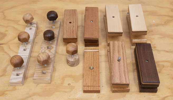
magnet cup limits the minimum diameter to about ¾”.  Here are a couple of photos of the turned and sanded blank.  To the left of the red arrow is the jig and to the right is the final turning sanded to 400 grit.  Last is to take the turning off the jig and break or soften the bottom edges as they are quite sharp.  One other item, on the left the number 4 on the jig matches the jaw number on the chuck.  That’s so when the jig goes back into the chuck it’s put in the same place every time. 

Below are the first four ready to be finished.

Next is to work with the other laminated block.  Rather than do a straight stack I decided to try some where the blank is cut out at an angle to the grain.  Here is the layout with two blanks at 30 degrees off vertical and two more at 45 degrees.  It should give a different look than the others.

This is the setup for cutting the blank for the 30-degree ones.  Once cut I took them to the disk sander to smooth out the faces.

After the faces are cleaned up the centers were marked so I could start the turning process.  That process will be the same as the first set. 

While rummaging through my stack of lathe stock I came across a roughly roundish piece that was gifted to me probably 20 years ago.  It’s a dark wood that is really, really hard and is probably some type of tropical hardwood, no idea what.  It seemed like a candidate for a design I had in mind so it got chucked up in the lathe, trued to a cylinder and parted for two blanks.  That’s what’s shown below.

Unfortunately, once the pieces were parted the ends looked like there was a split running right down the center.  When I checked by trying to pull them apart, they split right in half.  It was a clean split that looked like the pieces could be glued back together seamlessly.  Below is a photo of the two blanks after they were glued together but before they were put back in the lathe and turned.

Once turned the glue joint was all but invisible so the 
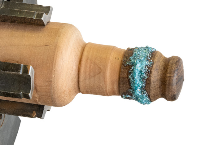
work progressed with the needed drilling and mounting on the jig.  The idea for this is once the blank was turned to its preliminary shape a narrow channel is cut in the blank then filled with a synthetic turquoise inlay.  Here is what that looks like.  Once the inlay thoroughly cures the blank will be turned to final size and the inlay polished.

After the inlay had cured the final turning could be done.  It all went well with the first piece with the inlay cutting smoothly but when turning the second one the tool caught a hard piece in the inlay and popped the ring out.  I have to say some rather testy words were said at the piece.  It did make me feel better but the inlay was still gone.  On the good side the wood was undamaged so the inlay could be replaced.  However, before doing that I did just a little more turning to the inlay’s slot tapering the slot so it was wider at the bottom than the top.  When I redid the inlay there was no problem in doing the turning so the taper must have locked the inlay in place.  I also sharpened the lathe tool so that probably had something to do with it too.  Here is what that piece looks like ready to be sprayed with lacquer.

On a whim I took some short pieces of cherry and maple out of the fire starter stack and glued them up in a block.  Once the glue cured the block got down cut with the bandsaw so the laminated layers would run across the blank at a 60-degree 
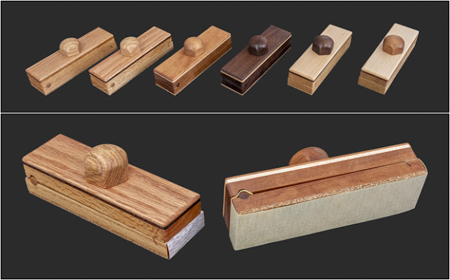
angle.  The top photo shows what the block looks like after being cut.  The usable blank is in the center and the angled pencil line represents the turning axis of the blank.  The bottom photo are the completed pieces.

I was getting ready to throw the cutoffs from this piece away when in looking at them I thought they could be put together is some sort of pattern.  On the left is what it looked like all glued up and on the right is the finished piece.

The finish for these is going to be lacquer sprayed on with the airbrush.  As I needed some way to hold them while being sprayed the easiest method is a dowel the same diameter as the magnet recess (5/8”) screwed to a base.  Not having a dowel this size some scrap pine was turned down on the lathe.

The dowel gets cut into 1” long pieces with the bandsaw and a pilot hole for the mounting screws drilled in its base using the lathe.

The dowels were then screwed to various bases and the completed turnings friction fitted on the dowels.  Here they all are ready to be sprayed with three coats of lacquer.

After spraying on the lacquer they were ready to have the rare earth magnets added.  The top photo below shows the cup and the screw that holds it in place plus the magnet itself.  The bottom left photo has the cup installed and the right photo is with the magnet in place.  Once the magnet goes into the cup it’s really, really hard to get it out again.

Below are photos of all 15 completed pieces.  It’s more than we need and more than I intended to make but got carried away with variations.  Then again, they probably will make a nice small gift.


If anyone wants to make these here is the sequence I used.

Fridge Magnets Sequence

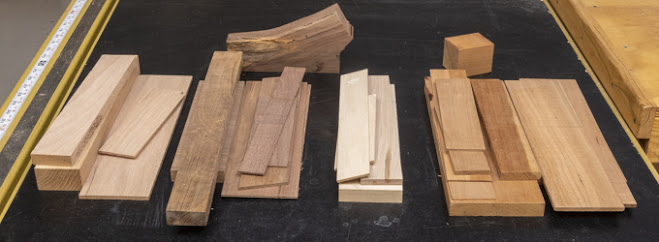
  1. Select stock or glue-up layers.  Size is dependent on finished size and orientation of grain needed in blanks   
  2. Cut into blanks between 1” to 1¼” square by 1¼” thick.  Generally completed pieces finished diameter is between 7/8” and 1 3/16” while height is between 1” and 1 3/16”.
  3. Mark center of piece on both sides. Use compass to layout completed diameter plus 1/8” or so.
  4. Rough cut outside line for blank.
  5. With sharp punch mark centers on both sides
  6. Use these marks for drive and live centers in lathe then turn round to a consistent diameter
  7. Put in 4 jaw chuck with drive end facing tale stock and align to lathe center line using drive center
  8. Drill 5/64” hole 5/8” deep using drill chuck in tailstock (for #6 screw in jig)
  9. Turn or sand this end square and true
  10. Drill 5/8” hole using flat bottom Fostner bit (brad point may work) depth of magnetic cup plus just a smidge
  11. Test fit cup to make sure it does not extend beyond wood base
  12. Screw end with holes to jig and lightly tighten in 4 jaw chuck, square using drive center in tail stock.  Once aligned tighten chuck securely
  13. Turn to desired shape remembering there is a 5/8” diameter hole in base and screw is 5/8” deep into blank
  14. Sand to 400
  15. Remove from jig and break bottom edges
  16. Apply finish
  17. Install cup & magnet

Monday, January 17, 2022

Fridge Magnets – #1 Preparing Blanks & Initial Turning

After making the Greene & Green end table along with the sanding blocks there was a fair collection of leftover, short fairly thin scraps.  I was getting ready to toss them in the “Designer Kindling” pile when I remembered that my wife has asked for some more refrigerator magnets.  Having been married for over 45 years one thing I have learned is that it’s always a good idea to make a project in the shop when asked.  First, a short description of these fridge magnets is needed.  These aren’t small light weight items that can barely hold up a single sheet of paper.  The magnet is a ½” diameter rare earth set in a steel cup that concentrates the magnetic field so it can hold up quite a bit.  The finished ones run from 7/8” to 1 1/8” in diameter and from 7/8” to 1 3/16” in height.

Here’s the pile of small scraps and thin pieces from the previous two projects plus some that have been setting around.  There is mahogany, oak, cherry, maple, walnut and leopardwood.  Now not all of them will be used but it’s my starting point.  There was also a couple of small blocks large enough to make solid ones but the rest will be laminated using the thin pieces.

After playing around with different wood species combinations two stacks were put together.  One stack consists of the following layers: maple, walnut, oak, mahogany, oak, walnut and maple whose finished size is 1”x 2”x 5½”.  The other stack is cherry, oak, cherry, oak and cherry whose finished size is 1 ¼”x 1 7/8”x 7”.  Neither are very large or have a lot of material in them but should give me several blanks.  Below are both of them glued up and clamped.

After the glue cures because all the layers never align perfectly the glue is cleaned off one long edge and the opposite edge trued up by taking a skim cut on the table saw.  That edge is then used to true up the first edge.  Last, both ends are cut on the chop saw to clean up any misaligned edges.  Here is what one of the blocks look like.

Taking the other block, I made a cut down the center of it with the bandsaw since it makes the thinnest kerf then laid out one magnet blank on either side.  The same layout is done on the opposite side since I need matching center points on both sides of the blank when it comes time to mount them in the lathe.

Cutting the blanks out on the bandsaw is next.  All that really needs to be done is to clip the corners to make is easier to turn it into a cylinder on the lathe.  Before laying out another set the rough bandsawn edge on the right end of the block gets squared up with the chop saw.

Before mounting the blank on the lathe the center points on both sides get a little dimple using a sharp punch.  They will be used to align the lathe’s drive and live centers.

Setting the drive center is next.  That’s done by putting the point of the drive center in the just made dimple and giving it a good whack using a wood mallet.  Here is the result.

With the drive center back in the lathe the blank is hand held against the live center in the tailstock and both are brought up to the drive center so its point aligns with the previously made set mark in the blank.  The tailstock is locked in place and pressure applied to the live center holding everything in place.

The rough blank is then turned to a smooth constant diameter.  It can be just brought down to a smooth cylinder or close to the final size but needs to be larger than the final size the reason which will get explained in a bit.  Here it’s just a smidge over the final size.

The cylindrical blank is removed from the lathe, the drive center taken off and a 4-jaw chuck put on.  With the drive end of the blank pointed toward the tail stock it’s lightly clamped in the chuck.  The tail stock is moved up to the blank end and the center point in the drive center is set in the indent.  That assures the center axis of the blank is aligned true to the lathe’s axis.  The photo below shows what that looks like.

Using a drill chuck mounted in the tailstock a pilot hole is drilled 5/8” deep with a 5/64” bit.  It’s for the screw that will hold the blank onto a jig.   One last thing to do is with the lathe is running look and see if this end of blank is square to the lathe centerline axis.  If not, it needs to be squared up before going on to the next step.

Drilling the recess for the rare earth magnet and its cup is next.  That’s done with a 5/8” diameter Fostner bit which leaves a flat bottom hole.  For the cup/magnet combination a hole just over ¼” deep is needed.  You want the edge of the steel cup to be just the tiniest bit below the bottom of the blank so it does not scratch the refrigerator door.  Last step here is to do final sanding to the bottom followed by a test fit of the magnet cup.

Next the blank gets screwed to the jig which is then mounted in the 4-jaw chuck.  The photo below shows the jig.  At the top is the screw that will hold the blank on and below that is a ¼” tall 5/8” diameter round tenon that snugly fits into the magnet recess that was just drilled.  The tenon helps center the blank on the jig.  Fine tuning of the centering is done the same as before using the drive center in the tail stock.

Here you can see why I mentioned that the turned blank needs to be just a little oversize before drilling.  The photo below shows the marks that the 4-jaw chuck leaves when the cylinder was clamped in place so the just completed drilling could be done.  They will be removed when the piece is brought down to its final shape.

Next Up – Finish Turning, More Variations & Finishing

Monday, January 10, 2022

Sanding Block - #5 Completing Knobs, Danish Oil Finish & Done

This post is a little longer that most because at the end I have included the sequence of operations including material and hardware sizes.

After turning the knob blank to a cylinder, marking the beginning point of the dome and the blank’s overall length the blank is turned down to final length.  With that done the dome part of the knob is turned.

Adding the six faces to the cylinder is next.  It did take a while come up with a process to get them the same size and 60 degrees apart.  First, a jig is needed to hold the knob in place while the face is made and second the jig has to be able to control the rotation of the knob (60 degrees) so the next face is in the proper orientation.  The top photo below shows the top of the jig.  On the right is business end that controls the location of the cut and its depth.  The hole is for the threaded rod while the partial hole on the left is where my thumb sets to control the depth of cut.  The bottom photo is the back side.  You can see where the threaded rod comes through.  A nut is used to tighten the rod which holds the knob in place.  The recess allows the threaded rod to be below the face of the jig.

Next the knob is mounted in the jig as shown in the top photo.  The bottom photo shows the first face completed.  I will show the jig in use and how the faces are made in just a bit.

With the first face made the nut holding the knob in place is loosened and the knob rotated 60 degrees clockwise.  The first face is now parallel to the long reference edge of the jig at the bottom of the photo.  The nut is tightened to hold the knob in place and the second face is made.  This is shown in the top photo.  This process is repeated to make the third face as in the bottom photo and continues until all six faces are made.

Here in both photos all six faces have been made.  The bottom photo is simply a different view of the knob and jig.

Now with an idea of how the knob and jig work together the only thing left out is to explain how the faces get made.  Of the options available using the disk sander seemed to make the most sense to me as the rate and amount of material removal is easily controllable.  The photo shows sander with the miter fence set so the jig presents the to be made face parallel to the disk.  In use the miter fence is moved back and forth to prevent the disk from burning the wood while the jig is gradually fed into the disk until the proper depth is reached. 

After the six faces are finished, they need to be sanded since the grit on the disk sander is certainly not smooth enough.  To maintain the flat face at the proper angle the knob is set in another jig and each face is sanded with 220 and 320 grit sandpaper to remove all traces from the disk sander. 

The last two bits of work on the knob is first to remount it on the lathe then hand sand to ease the transition between the dome and the faces then do the same thing with the sharp points between faces.  When done with the 320 paper the lathe gets reversed and the rounded edge between the faces gets sanded to make the feathering even on both sides.   Last the piece is removed from the jig and the edge between the faces and the base of the knob gets softened with sandpaper.

Everything went well except for the last knob.  When it was turned down to the cylinder, I saw a faint crack in the blank.  I had hoped that it would get turned away as the piece was cut to length and domed but no such luck.  The straw that broke the camel’s back was when the first face was made.  There right across the face was the crack that probably ran most of the way through the piece.  Not what I wanted but so it became scrap and another one made.  Looking back the knobs were the hardest most time-consuming part of the build as they were all made individually with little benefit of reusable machine setups. 

Below is what the five sanding blocks look like ready to apply three coats of Danish Oil Finish and buff out.  This type of finish is used rather than my usual lacquer as an oil finish can be rejuvenated down the line a lot easier than a film finish. 

Here are the pieces with one coat of Danish Oil Finish on them.  There are seven knobs because I made one to replace the prototype and ended up finishing the cherry one with the crack.

With all three coats of Danish Oil completed the cork bottom needed some attention.  No matter how careful when applying the finish invariably I got some on the cork.  The top photo is typical of what happened.  As I wanted to have an unfinished cork bottom it needed to be fixed.  Cleaning is pretty easy. a sheet of 220 grit sandpaper is clamped down to the table saw extension and a few passes cleans it up as shown in the bottom photo.

The top photo shows the five completed sanding blocks plus the prototype finished with the final buff done.  The bottom photo has two of the blocks with sandpaper loaded on them.  I know this project may seem like overkill for sanding blocks but I like working with nice tools and enjoyed the build. 

Once completed I built a storage case to hold them along with some cut sandpaper.  Five of the blocks are loaded with different grits of sandpaper from 80 to 400 grit.  In general, the darker the sanding block the finer the grit.  In addition, I wrote the grit on the end of the sandpaper.  This is what it looks like and will get mounted on the peg board for easy access. 

Early on I wondered if the parts would be interchangeable between the six blocks.  After giving it a try they are and if desired, the parts could be all mixed up and still work just fine.  Don’t think I will do that as I like the continuity of the woods but it is interesting that it would work.

For anyone who wants to make these here is the sequence of operations along with material sizes I used.

Sanding Block Sequence

  1. Thickness two blanks 2” x 7” x ½”
  2. Thickness two blanks 2” x 7” x 1/8” (one contrasting)
  3. Glue thin blanks to upper base
  4. Cut angled notch in lower base
  5. Glue cork to lower base
  6. Cut glued stack and lower base to 6.25” length and 1.83” width
  7. Sand cork on lower base to 5/8” total thickness and sand smooth edges
  8. Clamp upper and lower bases together, drill 5/16” dowel hole centered 13/32” from edge
  9. Turn 5/16” dowel
  10. Using dowel for registration drill 5/16” hole vertically through stack and just into base for ¼” rod
  11. Countersink underside of stack with ½” Fostner bit 1/8” deep
  12. Drill 10 mm hole in base for insert & chamfer
  13. Temporarily install ¼"-20 brass insert & remove
  14. Finish sand base upper face
  15. Glue in dowel
  16. Sand excess off dowel ends
  17. Epoxy insert in place
  18. Route top edges of stack
  19. Final sand top stack
  20. Finish using DOF

Sanding Knob Sequence

  1. Layout knob blanks, 1 5/8”+ diameter with compass.  Drill 7/32” hole 5/8” deep for rod.
  2. Bandsaw knob to rough circle
  3. Cut 1¾” long ¼”-20 threaded rod
  4. Thread knob hole & epoxy rod into knob blank
  5. Put fixture in lathe and use live center to true center
  6. Do not take fixture out of lathe, take chuck & fixture off lathe then put cap in fixture
  7. Turn to a 1 37/64” diameter cylinder
  8. Turn dome shape total 7/8” tall with lower ½” still a cylinder
  9. Take chuck off lathe, remove knob & install in jig
  10. Sand 6 flats with jig on disk sander, remove from jig
  11. Use sanding jig to sand flats to 320
  12. Put back on lathe fixture then using 120, 220 & 320 sandpaper feather dome & edges between flats knocking of sharp edges.  At very end reverse lathe and sand with 320 to help feather both edges
  13. Remove from lathe fixture and break base to face surface


Monday, January 3, 2022

Sanding Block - #4 Installing Insert, Gang Routing & Knobs Part 1

Final sanding of the top of the base using 220 grit sanding paper is next.  That’s followed by gluing and clamping the dowel in place in the photos below.

After the glue cures the dowels which are just a tad long are sanded flush with the base.  The large disk sander with a guide to keep the base square with the disk is used.  That’s followed by sanding the sides and ends down to 220.

With the dowels flushed to the sides and all sides finish sanded the brass insert can be epoxied in place.  A small amount of the epoxy is spread on the sides of the hole in the base.  The insert is run in with the ground off end put in first until it bottoms out.  That’s done using a short bit of threaded rod that has a couple of jam nuts on it chucked up in a drill. 

Below in profile you can see how the insert sticks up above the top of the base and that’s why earlier a countersink was added to the underside of the top.  Without it the top wouldn’t be able to clamp down on the sandpaper holding it in place.

While the epoxy cures the 3-layer top stack gets its top edges and corners rounded over for a softer feel in the router with a 1/8” radius bit.  The corners get done first because they are end grain which is prone to chipping when the router bit exits the cut.  That’s solved by using a scrap backup piece.  Another consideration is that the pieces will be on their narrow edge when routing and could be prone to tipping which is solved by clamping it to a wide block for stability.  Clamping to the wider block also helps guide the piece across the router bit as the opening in the fence is wider than the piece.  I did add a second larger push block to the right to provide some additional stability for peace of mind.  It worked well on the single prototype so when routing the rest they all got clamped together and routed in one pass.  The setup below shows everything ready to go.  The long edges are easy to route using a push block to keep my fingers away from the bit.  Once routed all the surfaces get sanded. 

When I did the prototype the knob that clamps the sandpaper in place is domed as in the photo below on the left.  It was acceptable but I wanted a shape that provided a better grip and felt good in palm of my hand and didn’t want any sharp edges.  Lots of ideas came to mind but all had one or more flaws.  A shape that did occur to me in the middle of the night is similar to what’s called an Acorn nut shown on the right.  With that shape in mind, it’s back to the prototype stage figuring out how to make a domed hexagon.  Once I got a finished prototype it’s time to make five more.

The process starts by laying out a 1 5/8” diameter for the knob with a compass.  Here are the oak, cherry and walnut blanks to be used.

Next, it’s over to the bandsaw to cut the rough knob blanks out.  The bandsaw has a ½” wide blade on it which is too wide to make a 1 5/8” diameter cut.  If I changed it out to a ¼” one there would be a lot less burning and a smoother cut since a ¼” blade can cut a tighter radius.  However, it takes a while to change the blade and adjust the six blade guides.  Besides these are all going to be turned round on the lathe so it’s not a big deal.

After rough cutting the blanks out on the bandsaw a 7/32” hole 5/8” deep is drilled for threaded rod.  The 7/32” diameter is a little odd size but it is just slightly less than the diameter of the ¼” threaded rod.  I do that so some shallow threads get cut into the knob when doing the initial install of the rod.  That’s done by using the drill press, rotated by hand, to make sure the rod is square and true to the underside of the knob.  That's so when it gets tightened the knob lays flat against the top of the sanding block.

Sizing a section of threaded rod that will get epoxied in the knob is next.  The procedure is a little more involved than just using a bolt cutter or hack saw to cut the rod to length.  Either one of those damages the threads at the cut making it hard to start in the brass insert and I want the rod to easily start and have no sharp edges at the cut.  The photo below shows the threaded rod clamped in place with a piece of tape marked with the 1¾” length needed.  On the left is a ¼-20 die that will be used to chase the threads after the cut.  Also, in the background you can see three finished pieces ready to be epoxied in place.

This is after the rod has been cut and you can see the resulting burr on both pieces.  From here the long rod is removed from the clamp, the rough end ground smooth and the die spun off the rod to reform the threads.  Last, the short section of rod to be used gets its end cleaned up by grinding the rough end smooth then running the die from the good end to reform the threads.

Next the sized threaded rod is epoxied in the cap place making sure 1 1/16” of rod is exposed.  A pair of jamb nuts and a wrench lets me run them in.

After the epoxy cures overnight the cap assembly is threaded in a lathe fixture made specifically for this purpose and a nut is put on the threaded rod from the inside locking the assembly in place.  The top photo shows the rough blank mounted and the bottom one it turned down to a cylinder.  The left white line is where the dome part of the knob starts and the right line is the overall height.

In checking there was a problem with one knob where the end of the blank was not square with the threaded rod.  No idea why but it did need to be trued up so it will lay flat on the sanding block’s body when tightened.  Fortunately, it was not hard.  Below shows the lathe setup.  From the left a drill chuck clamps onto the threads but not so tight that it deforms them.  Next is a couple of jamb nuts on the threaded rod that are tight to the jaws of the chuck.  To the right of the knob is the lathe’s tail stock.  It has a live center mounted in it that applies pressure against the knob which gets transmitted to the jamb nuts providing enough friction against the chuck that the face can be turned true.  That’s as long as the tools are sharp and a light touch is used.

Next Up – Completing Knobs, Danish Oil Finish & Done