Router Plane

Monday, April 24, 2023

Segmented Bowl – # 8 Thin Layers & Cutting Segments

The next four layers to be made are much thinner that the others which presents some different problems.  The drawing below has layers numbered 8 and 10 highlighted in blue.  What’s not shown is each of these layers is made up of two rings, one oak and one cherry layer right at 1/8” thick.

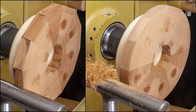
Because these layers are so thin the hose clamp used to pull the segments together has a tendency to slip off as it is tightened.  Getting around that problem required making the jig shown below.  Four spacers just 1/64” taller than the hose clamp’s band gets clamped to the jig.  This lets the segments and the hose clamp move around as the hose clamp gets tightened but keeps the hose clamp from riding up and popping off the segments.  The right photo is a little closer view.

Another problem with the thin segments is that when the hose clamp is tightened the segments do not lay flat but get a little wavy.  That’s solved by using a piece of MDF as a caul after first laying down a sheet of 6 mil polyethylene plastic on top of the segmented ring.  The plastic keeps the ring from getting glued to the MDF.  With the MDF caul in place, the red handled clamps are snugged down, the hose clamp tightened and the red handled clamps tightened the rest of the way.  Here is what all that looks like completed.

Since all four of the layers are the same size, I decided to cut the segments all at once while the tablesaw jig is setup then do the four glue-ups using the gluing jig before moving on.  The down side is because I let the glue cure overnight it takes four days to glue-up the rings.  Once all four all done, they get run though thickness sander.  However, since they are thin and a bit fragile a carrier with support blocks shown here is used to support and hold them while being run through the sander. 

Here the four rings are sanded, done and ready to be glued on.

Gluing on the thin cherry and oak rings are next.  They follow the same procedure as the others with one exception.  Since the ring is somewhat flexible the MDF caul is used (red arrow) to keep the layer flat with the polyethylene between it and the layer to make sure the MDF and the ring don’t accidently get glued together.  The same process is used for the next thin oak ring.

Cutting the already made blocks in segments for the four feature rings takes a little planning so they come out nice and flat when glued-up.  When making the regular rings the board is flipped top to bottom after each cut.  In the photo below you can see the cutting jig on the table saw with one piece cut and three cut pieces lined up near the bottom.  When these pieces are assembled into a ring, they will lay flat even if the saw blade is not absolutely set at 90 degrees to the table because if there is an error it gets cancelled out by the way the segments are cut.  Bear with me for a bit as I go through how this works and why it’s important when cutting the segments for the feature rings.

As much as I try, I know the table saw blade is not absolutely perfectly 100% square with the table.  It’s very close, close enough so I can’t measure an error when making a cut.  However, because the rings are made from 12 segments there are 24 cuts and any error when making a cut gets multiplied twenty-four times so a really small error gets magnified a lot.  As an example, let’s assume that the blade is off an exaggerated amount of say 10 degrees like in the drawing below.  When the end cut is made as in the bottom photo the edge of the segment ends up with the jig’s 15-degree angle plus the 10 degrees the saw is out of square.

Next the board is flipped top to bottom, slid over to the stop and the segment is cut to length which is the piece to the right of the saw blade in the top drawing below.  This piece’s edges are not square and do not have parallel edges.  To make the second segment the board is flipped top to bottom and then the second segment is cut with the results shown in the middle drawing below.  Last is to flip the just cut segment top to bottom which is shown in the bottom drawing.  Now when the two cut pieces are glued together the angled edges of the segments cancel each other out resulting in a flat glue up.

This method only works when the segments get cut from a continuous board but the feature rings are not made from a continuous board, they will be made from the already rough sized individual blocks. 

The first segment follows the same process as the ones in the regular rings.  First, one end is trimmed using the jig to make the 15-degree angle shown in the top photo.  If you look in the saw slot in the jig you can just see a line that represents the cut of the hypothetical 10-degree out of square saw blade.  The piece is then flipped top to bottom and the other end cut to make the tapered segment (bottom photo).  On the vertical face the pencil lines show how the piece would look like a wedge.  Now if the next piece were cut the same way that wedge shape would compound and not cancel out.  The result is when the segments glued together a shallow cone would be created rather than a flat ring.

In order to make a segment with complimentary angles to the first one I need to reverse the cuts or make the first cut with the blank’s bottom face up rather than down like the first one.  That setup is shown in the top photo.  Note that this blank has the maple side up rather than the previous piece which started with the cherry face up.  After the first cut the blank is flipped top to bottom and the second cut made per the bottom photo.

Put side by side you can see when the cuts are made as described above the adjoining faces (red arrows) will cancel out any minor variances from a non-square saw blade.  The result is a self-compensating joint that will mesh creating a flat glue-up.  Now all I need to do is make sure that all the even numbered blanks are cut one way and the odd numbered ones the other.

Next Up – Making Feature Ring Segments

Monday, April 17, 2023

Segmented Bowl – # 7 Assembling the Base Parts & Adding Layers

Before gluing the oak ring onto the base cherry ring there is one last step.  To remove any problem with expansion and contraction due to humidity changes the disk needs to float freely in the recess.  If a finish is put on the oak disk and the recess the disk won’t get securely glued in place if I get a little sloppy with the glue when adding the oak ring.  Here the left photo shows the recess for the cherry ring with the finish applied.  Wipe-On polyurethane is used rather than my usual lacquer finish for reasons I will get to when the finish is applied to the turned bowl.

Here is the disk with the finish applied, dry and ready to be added.

Assembly is next with the left photo showing the cherry base with its recess, the oak disk that goes in it and the oak ring that gets glued on.  On the right is after the oak ring has been glued and clamped on.  Note how the 2” Fostner drill bit is being used to center the oak ring.

Laying out most all the pieces needed for the different rings is next.  I did spend some time juggling the pieces to get the most efficient material use.  I guess playing Tetris did have a good use.  The top photo shows how the main plank gets divided up into pieces for eight different rings.  Most of the pieces worked out so the plank could be crosscut to a common length but one set of pieces didn’t so it got separated into two dogleg pieces using the jig saw.

Next is to cut those pieces to width so they can be cut into segments to make the rings.  The process in doing that is the same as already discussed.  Here in the foreground is one set of segments ready to have glue applied, one ring ready to be flattened and one ring clamped while the glue dries.  In the background are blanks for other rings.

The rings are flattened and brought to final thickness using the thickness sander.  The top photo shows the ring marked with pencil lines so when the piece is sanded I can easily see those areas that are still low as they still have the pencil marks on them.  Once all the marks are gone the surface is leveled.  Same process is used on the other side so I end up with flat parallel faces.  In the bottom photo the two left rings are sanded and ready to be glued onto the bowl stack.  The right ring is clamped and waiting for the glue to cure.

After letting the glue joint between the cherry base and the first oak layer cure the oak layer can be turned round.  The left photo has had a little done to knock off the corners and the right photo is the turning in progress.

With the oak layer turned round I can use it to center the next oak layer.  In the left photo after careful measuring the glued-up assembly is centered on the next layer and the outline of the assembly marked on the to be added oak layer.  The right closeup photo shows the pencil line and a reference mark used for aligning the layers.

Once the glue is spread the pieces are aligned and clamped together.  Since the glue acts like a lubricant it’s pretty common for the pieces to move as the clamps are tightened so extra care has to be taken make sure they stay aligned.

For the next few layers, it’s the same process of turning the previous layer round, using it to center the next layer and gluing that one on.  Earlier on I mentioned when centering the layer there was some careful measuring to get it done.  Here for the fifth layer, it seems like a good time to go into a little more detail on how that’s done.  The photo below shows after the layer stack has been centered left to right with a couple of clamps used to hold it in position.

Next the same process is used to center the layer stack top to bottom.  That’s shown done in the photo below.  This process of centering the bowl along one axis at a time speeds the centering up a lot since the first two clamps hold it in place when you go to center the second axis.  Otherwise, it can be a long process of getting one axis right then accidently shifting it when making a change to the other axis where you end up chasing the centering.  Before calling it done the joints of the new layer are checked to make sure they line up with the previous layer.  If they don’t something is wrong.

Last is to mark a center line between two of the segment edges then rotate the layer stack until the joint in the rounded layer lines up with centerline. 

In order to give myself a limit to where the glue gets applied the stack along with the new layer is clamped together, flipped over and the inside outline of the new layer is traced onto the underlying layer.  Here is what the traced line looks like so now I know where my glue application limit is.

The last step before gluing up is to do a little preliminary turning to the inside of the bowl.  In this photo you can see how the layers are getting blended together.  Now this is in no way the finished interior profile of the bowl but it is a start.  Once the blending is done the next layer gets glued on.  I will get to smoothing the outer layer later but now I need the layer steps there to provide me some place for the clamps to go when adding layers.  After this layer there is only one more full thickness oak one to go before there will be a shift in material and layer thickness.

Here the next layer has been added.  One step not shown in the layer adding process is to make sure the layer’s face has no runout or wobble along the lath’s axis.  Because the layers are sanded smooth and parallel before gluing on, they are mostly true after being glued on.  Generally, it takes just some final sanding using an oak scrap with sandpaper at the end for truing although a little touchup with a scraper is sometimes needed.  When sanding the oak sets on the lathe rest with the sandpaper against the surface and the other end just touching the face.  Light sanding until the chalk is gone gives me a flat smooth glue surface for the next ring.

Next Up – Thin Layers & Cutting Segments

Monday, April 10, 2023

Segmented Bowl – # 6 Aligning Bottom Layer & Fitting Plywood Insert

After the glue cures the clamps are removed and the assembly is put on the lathe.  The left photo shows it ready to go and the right one shows a circle in pencil marked with the lathe spinning and is centered on the piece.  Here is where all the careful measuring and assembly comes together in that the hole almost perfectly centered.

Turning the first layer or base of the bowl round gets rid of all the corners.  The left photo is before I started turning and you can clearly see the corners plus the flats between them.  The right photo is after the corners are turned off along with a nice little pile of shavings removed.

Next is to take a skim cut off the face of the layer to make sure the face is square with the lathe’s axis.  That’s followed by rounding the twelve-sided hole at the center of the base and cutting a recess for the floating plywood base that’s been curing for a while.  In the top drawing the disk is in blue and the white is the base layer that has a notch cut in it for the plywood.  There are a couple of ways to round out the base’s hole.  I could have used lathe tools and carefully measure the hole to get it to the 2” diameter needed or just use a 2” Fostner bit.  Guess which is easier and probably more precise?  The bottom photo shows after the 2” bit has bored a nice centered, straight sided round hole.  Cutting the recess is next.  That will be done with the 2 ½” bit shown here.  Looking closely at the base you can see the initial scoring cut.  All that has to be done is to run the bit in until the recess is the same thickness as the plywood disk.  For now, I will only go about 1/8” deep in order to give me a shallow recess to work with so the disk can be sized to fit.

This set of photos shows the oak plywood face on and also an edge view where the three layers are easily visible.  The dial caliper shows the thickness is about 1/64” less than 3/16” thick.

As the recess in the cherry base layer is 2 ½” in diameter I want the disk to be just a little less than that.  A couple of concentric circles are drawn on the oak plywood for reference, one at 2 ½” and one a little less.  Cutting the piece out is done on the bandsaw.  This is what the finished cutout looks like.  The jagged cut is because the ½” blade I have on the bandsaw won’t cut a circle that small so regular relief cuts are made as I work my way around.  From here the disk is taken to the large disk sander and the shape refined until it fits into the recess with just a little play.

The left photo shows the disk fitted to the diameter of the recess with the recess itself deep enough so the disk is just level with the top of the cherry layer.  The right photo is without the disk.

Making the second layer from the bottom or #15 is next.  Since the blanks have already been cut to thickness all that’s needed is the width which from the chart is 3 ½”.  The total blank length needed is 19.841” or about 20” and both are highlighted in the spreadsheet below.  I have a wide cutoff that’s about three quarters of the total length that matches the material selected so ripped it into two blanks and cut the segments from them.   

Cutting the segments and gluing them together follows the same process as the cherry base so I won’t go through that again but below is the glued-up ring.  This ring needs to have the twelve-sided hole in its center rounded out to a 2” diameter hole and that’s next.

To round the hole the same 2” bit is used that drilled the cherry base.  The problem is locating the center of the hole.  That’s solved but putting a couple of layers of tape over the hole then using a compass set close to the rings radius to draw several arcs made from different corners.  The center of those arcs gives me the center point.  In the photo I used an awl to poke a small reference hole through the tape.

After flipping the ring over you can see how the reference hole looks centered in the opening.

The hole will be made on the drill press.  In the top photo the centering pin is used to get the ring in the right position followed by clamping it in place prior to changing out the pin, installing the bit and drilling the hole.  The bottom photo is a close view after the hole is cut almost all the way through.  In looking at what’s left to be removed it is concentric to the drilled hole which is a good sign.

Aligning the oak ring to the existing cherry ring is next.  The same 2” drill bit that made hole in both pieces is chucked in the lathe and used as an alignment guide.  The left photo shows how the bit aligns both pieces.  Doing it this way makes sure they are centered on the lathe’s central axis allowing me to turn them concentric about that axis.  The right photo shows how the two rings overlap.  For reference there is a “A” marked on both rings.  The pencil line on the cherry ring is half way between segment joints and that will line up with the oak segment joint offsetting the layer by half.  To center the oak ring on the cherry ring I did trace the outline of it on the oak ring.  The bit can’t be used to align both rings because the oak plywood disk will be inserted in the recess preventing access to the cherry ring.

Next Up – Assembling the Base Parts & Adding Layers

Monday, April 3, 2023

Segmented Bowl – # 5 Making and Mounting the Bottom Layer

Referring to the spreadsheet for the bottom layer (#16) that row has the needed information highlighted in yellow.  The blank for the segments needs to be 2 ½” wide, roughly 16 ¾” long with a finished thickness of 7/16” and is made from cherry. 

For reference since the Width and Outer Face Length are not necessarily obvious the drawing below should clarify that.

Here are the blanks for layers 15 and 16.  Normally they would be a single piece but in this case layer 16 is from the leftovers from the feature layer and layer 15 was a short board that matched the oak plank that will be used for the bulk of the bowl’s oak layers.  Two items to mention on the thickness.  The finished thickness of layer 16 will be 7/16” but this piece is thicker than that because of the way it is attached to the sub-base layer that’s attached to the lathe’s face plate.  More on that in a bit.  Layer 15 finished thickness is to be 3/8” and it’s now a bit over ½”.  The final thickness is obtained by ripping the oak board on the bandsaw then running it through the thickness sander to smooth the bandsawn face.

The blanks get cut into segments using the table saw and this jig made to cut an exact 15-degree angle.  The two white pieces sticking out the top and bottom of the jig are polyethylene runners that fit in the table saw’s miter fence slots.  They align the jig so matching repetitive cuts can be made.  Here the end cut (red arrow) has been made to establish the initial 15-degree angle.

This is a closer view of the jig’s business end where the segments are cut to their Outer Face Length.  The red arrow points to the pencil line that marks the required length.  The silver clamp holds a stop block in place so all the segments are cut the same length.  Once this cut is made the segment is removed, the blank flipped top to bottom, put back in the jig and the next one is cut.

Here there is one piece cut in the jig along with three other cut pieces that shows how the blank gets cut.  I number them so when they get glued up, I know which side is up and what order to put them together to make the ring.

Here are all twelve segments cut and ready for a test fit. 

In order for the bowl to look right the joints between the segments need to match exactly.  Absolutely no gaps between pieces are allowed.  The left photo shows all twelve of the segments clamped together normally lit.  Here everything looks good but viewing it like this can be deceiving.  To make sure there are no gaps the assembly is held up against the light as shown in the right photo.  If there are any gaps then the sun will shine between them and corrective measures are required.  In this case there are no gaps and all the segments can now be glued together.

Rather than trying to spread glue on each piece I camp them all together and then spread the glue on all the segments at once.

After the glue is spread the clamp comes off and the segments are put together to form the ring.  To make sure there is a good bond I do rub each segment against its neighbor as they are put in place.  When all assembled a hose clamp is used to pull everything tight together then the joints are all checked to make sure they are flush with each other.  The top photo shows that all done.  Last is to clean off most of the glue and set the assembly on edge to cure as in the bottom photo.

After an overnight cure the clamp gets removed and the ring looks like the photo on the left.  A few passes on each side through the thickness sander removes the glue and flattens the disk so it looks like the photo on the right.  It’s set aside for a bit while the mounting base gets worked on.

The mounting base consists of two pieces; the lathe’s face plate and a piece of 2x6 that has been flattened either by running it though the jointer or the planer as shown in the first post.  I could just mount the block on the lathe’s face plate and turn it round but it’s easier to cut those corners off so it’s close to being round then turn it smooth.  Here it is bandsawn roughly to size.

Screwing the face plate to the mounting block is next.  To center the face plate a Fostner bit the same size as the hole in the center of it is used.  The top photo shows the bit inserted in the face plate and all that’s needed now is to put the point of the bit into the center punched mark on the mounting block.  The bottom photo shows that done.  To make sure the screws holes are centered in the face plate holes a Vix bit is used, here already mounted in the drill.

The mounting block is then screwed securely to the face plate (left photo) with six #8 x 1¼” screws.  It’s then mounted onto the lathe, the outer rim turned to a true circle and the face turned until it’s flat and square with the lathe’s axis.

While still on the lathe some concentric circles are marked on the lathe that are slightly larger and smaller than the hole in the cherry base layer.  The cherry layer is set on the base to check and make sure the layer can be centered on the base.

Gluing the cherry layer to the base assembly is next.  Since the glue make things a bit slippery, I have to be very careful to make sure the cherry layer stays centered on the base.  Plenty of clamps are used to insure a good glue joint with no gaps.

Next Up – Aligning Bottom Layer & Fitting Plywood Insert