Referring to the spreadsheet for the bottom layer (#16)
that row has the needed information highlighted in yellow. The blank for the segments needs to be 2 ½”
wide, roughly 16 ¾” long with a finished thickness of 7/16” and is made from
cherry. 

Here are the blanks for layers 15 and 16. Normally they would be a single piece but in
this case layer 16 is from the leftovers from the feature layer and layer 15
was a short board that matched the oak plank that will be used for the bulk of
the bowl’s oak layers. Two items to
mention on the thickness. The finished thickness
of layer 16 will be 7/16” but this piece is thicker than that because of the
way it is attached to the sub-base layer that’s attached to the lathe’s face
plate. More on that in a bit. Layer 15 finished thickness is to be 3/8” and
it’s now a bit over ½”. The final
thickness is obtained by ripping the oak board on the bandsaw then running it
through the thickness sander to smooth the bandsawn face.
The blanks get cut into segments using the table saw and
this jig made to cut an exact 15-degree angle.
The two white pieces sticking out the top and bottom of the jig are polyethylene
runners that fit in the table saw’s miter fence slots. They align the jig so matching repetitive
cuts can be made. Here the end cut (red
arrow) has been made to establish the initial 15-degree angle.
This is a closer view of the jig’s business end where the
segments are cut to their Outer Face Length.
The red arrow points to the pencil line that marks the required
length. The silver clamp holds a stop
block in place so all the segments are cut the same length. Once this cut is made the segment is removed,
the blank flipped top to bottom, put back in the jig and the next one is cut.
Here there is one piece cut in the jig along with three
other cut pieces that shows how the blank gets cut. I number them so when they get glued up, I
know which side is up and what order to put them together to make the ring.
Here are all twelve segments cut and ready for a test
fit.
In order for the bowl to look right the joints between
the segments need to match exactly.
Absolutely no gaps between pieces are allowed. The left photo shows all twelve of the
segments clamped together normally lit.
Here everything looks good but viewing it like this can be deceiving. To make sure there are no gaps the assembly
is held up against the light as shown in the right photo. If there are any gaps then the sun will shine
between them and corrective measures are required. In this case there are no gaps and all the
segments can now be glued together.
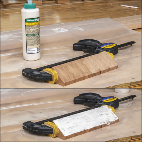
Rather than trying to spread glue on each piece I camp
them all together and then spread the glue on all the segments at once.
After the glue is spread the clamp comes off and the
segments are put together to form the ring.
To make sure there is a good bond I do rub each segment against its
neighbor as they are put in place. When
all assembled a hose clamp is used to pull everything tight together then the
joints are all checked to make sure they are flush with each other. The top photo shows that all done. Last is to clean off most of the glue and set
the assembly on edge to cure as in the bottom photo.
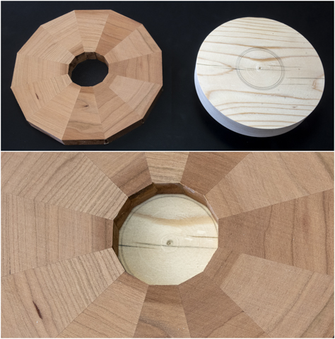
After an overnight cure the clamp gets removed and the
ring looks like the photo on the left. A
few passes on each side through the thickness sander removes the glue and
flattens the disk so it looks like the photo on the right. It’s set aside for a bit while the mounting
base gets worked on.
The mounting base consists of two pieces; the lathe’s
face plate and a piece of 2x6 that has been flattened either by running it
though the jointer or the planer as shown in the first post. I could just mount the block on the lathe’s
face plate and turn it round but it’s easier to cut those corners off so it’s
close to being round then turn it smooth.
Here it is bandsawn roughly to size.
Screwing the face plate to the mounting block is
next. To center the face plate a Fostner
bit the same size as the hole in the center of it is used. The top photo shows the bit inserted in the
face plate and all that’s needed now is to put the point of the bit into the
center punched mark on the mounting block.
The bottom photo shows that done.
To make sure the screws holes are centered in the face plate holes a Vix
bit is used, here already mounted in the drill.
The mounting block is then screwed securely to the face
plate (left photo) with six #8 x 1¼” screws.
It’s then mounted onto the lathe, the outer rim turned to a true circle
and the face turned until it’s flat and square with the lathe’s axis.
While still on the lathe some concentric circles are
marked on the lathe that are slightly larger and smaller than the hole in the
cherry base layer. The cherry layer is
set on the base to check and make sure the layer can be centered on the base.
Gluing the cherry layer to the base assembly is
next. Since the glue make things a bit
slippery, I have to be very careful to make sure the cherry layer stays
centered on the base. Plenty of clamps
are used to insure a good glue joint with no gaps.
Next Up – Aligning Bottom Layer & Fitting Plywood Insert

No comments:
Post a Comment