
After the glue cures the clamps are removed and the assembly
is put on the lathe. The left photo
shows it ready to go and the right one shows a circle in pencil marked with the lathe spinning and is centered on the piece. Here is where all the careful measuring and
assembly comes together in that the hole almost perfectly centered.
Turning the first layer or base of the bowl round gets
rid of all the corners. The left photo
is before I started turning and you can clearly see the corners plus the flats
between them. The right photo is after
the corners are turned off along with a nice little pile of shavings removed.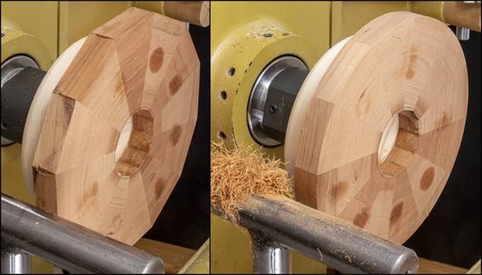
Next is to take a skim cut off the face of the layer to
make sure the face is square with the lathe’s axis. That’s followed by rounding the twelve-sided
hole at the center of the base and cutting a recess for the floating plywood
base that’s been curing for a while. In
the top drawing the disk is in blue and the white is the base layer that has a
notch cut in it for the plywood. There
are a couple of ways to round out the base’s hole. I could have used lathe tools and carefully
measure the hole to get it to the 2” diameter needed or just use a 2” Fostner
bit. Guess which is easier and probably
more precise? The bottom photo shows
after the 2” bit has bored a nice centered, straight sided round hole. Cutting the recess is next. That will be done with the 2 ½” bit shown
here. Looking closely at the base you
can see the initial scoring cut. All
that has to be done is to run the bit in until the recess is the same thickness
as the plywood disk. For now, I will
only go about 1/8” deep in order to give me a shallow recess to work with so
the disk can be sized to fit.
This set of photos shows the oak plywood face on and also
an edge view where the three layers are easily visible. The dial caliper shows the thickness is about
1/64” less than 3/16” thick.
As the recess in the cherry base layer is 2 ½” in
diameter I want the disk to be just a little less than that. A couple of concentric circles are drawn on
the oak plywood for reference, one at 2 ½” and one a little less. Cutting the piece out is done on the
bandsaw. This is what the finished
cutout looks like. The jagged cut is
because the ½” blade I have on the bandsaw won’t cut a circle that small so
regular relief cuts are made as I work my way around. From here the disk is taken to the large disk
sander and the shape refined until it fits into the recess with just a little
play.
The left photo shows the disk fitted to the diameter of
the recess with the recess itself deep enough so the disk is just level with
the top of the cherry layer. The right
photo is without the disk.
Making the second layer from the bottom or #15 is
next. Since the blanks have already been
cut to thickness all that’s needed is the width which from the chart is 3
½”. The total blank length needed is
19.841” or about 20” and both are highlighted in the spreadsheet below. I have a wide cutoff that’s about three
quarters of the total length that matches the material selected so ripped it
into two blanks and cut the segments from them.

Cutting the segments and gluing them together follows the
same process as the cherry base so I won’t go through that again but below is
the glued-up ring. This ring needs to
have the twelve-sided hole in its center rounded out to a 2” diameter hole and
that’s next.
To round the hole the same 2” bit is used that drilled
the cherry base. The problem is locating
the center of the hole. That’s solved
but putting a couple of layers of tape over the hole then using a compass set
close to the rings radius to draw several arcs made from different
corners. The center of those arcs gives
me the center point. In the photo I used
an awl to poke a small reference hole through the tape.
After flipping the ring over you can see how the
reference hole looks centered in the opening.
The hole will be made on the drill press. In the top photo the centering pin is used to
get the ring in the right position followed by clamping it in place prior to
changing out the pin, installing the bit and drilling the hole. The bottom photo is a close view after the
hole is cut almost all the way through.
In looking at what’s left to be removed it is concentric to the drilled
hole which is a good sign.
Aligning the oak ring to the existing cherry ring is
next. The same 2” drill bit that made
hole in both pieces is chucked in the lathe and used as an alignment
guide. The left photo shows how the bit
aligns both pieces. Doing it this way
makes sure they are centered on the lathe’s central axis allowing me to turn
them concentric about that axis. The
right photo shows how the two rings overlap.
For reference there is a “A” marked on both rings. The pencil line on the cherry ring is half
way between segment joints and that will line up with the oak segment joint
offsetting the layer by half. To center
the oak ring on the cherry ring I did trace the outline of it on the oak
ring. The bit can’t be used to align
both rings because the oak plywood disk will be inserted in the recess
preventing access to the cherry ring.
Next Up – Assembling the Base Parts & Adding Layers
No comments:
Post a Comment