Router Plane

Monday, August 28, 2017

Frank Lloyd Wright Desk Lamp - #4 Center Column, Boxes & Baffles

To cut the dado in the column I used my stacking dado set assembling two outside cutters and two inside chippers.  With that in place I set the height at ¼” then with some very careful measuring set the rip fence so the dado was centered on the piece.  A pass through the table saw and I had half the chase cut.  Another pass on the second half and I was done.

Here are some photos of what the chase looks like apart and clamped together for one last check before gluing up.


Next is to glue the column up.  I applied a coat of glue keeping it back from the edge of the chase to minimize the glue squeeze out that could run into the chase and clamped it all together.  This is the same photo as the test clamp and I used the same clamps in the same order as then so did not take another photo.  OK, actually I just forgot to take a photo when I had it all clamped up but really it did look the same.


After letting the glue cure overnight, I took off all the clamps and checked the column to make sure it was straight.  The result was mixed news.  Along the set of faces that had the glue joint things looked really good.  However, the other two faces have a bit of curve to them.  The column is just under 2” wide and 44” long with maybe 4 or 5 hundredths of an inch gap in the center.  Not much but enough that I wanted to correct it.

I don’t have a jointer and the curve is to gentle for my long hand plane to take care of so I have to use a different method.  I start by taking my 8’ level and clamping it to the fence on the table saw.  That gives me a straight edge more than twice the length of the column.  This means I can take the column then set the high points against the level so the curve shows up as a gap between the level and column.   Next the width of cut is set so it just barely skims the end of the column.  As the piece moves down the level the cut removes the curve and I end up with a face as straight as the level.  Flipping the piece over I set the newly trued face against the level reset the width of cut to skim a bit off and make the cut.  It took a couple of times resetting the fence since I was trying to remove the high ends and just graze the bottom of the curve. 


Setting the column aside to see if was going to remain flat I took the cutoff from the board the column was made from cut it slightly over the column width and glued up about a 14” long solid blank for the cap.  I only needed a 2” piece but something that short is dangerous and difficult to machine.  The excess will not go to waste I will keep it as a turning blank to be used on the lathe for something later.


With that done I could get started on roughing out the 
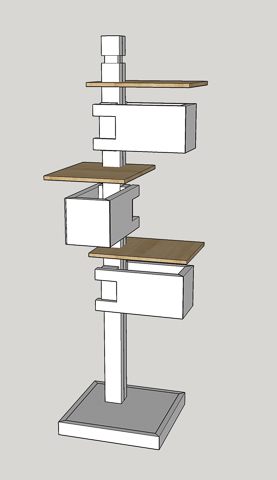
boxes and spacers.  The left hand drawing at right shows the boxes highlighted.  The right hand one has the spacers highlighted.

From the original board, I had enough material for two of the boxes.  The third needed to come from another board.  As you can see the left board end is in pretty poor condition.  The good news is that it is nearly one inch thick so I have some material to work with and clean up.   Besides the pieces for the boxes I had some cutoffs that were big enough for the spacers.


Following the same process as before I cut to rough length, hand planed 1 straight edge, ripped to rough width, checked for warp (none found) cup (a little) and bow (a tiny bit).  Next is using the thickness sander and 80 grit paper to remove defects, flatten and get to a consistent thickness.  When done here are the parts for everything except for the base.


After letting the column set for a few days I checked it for straight, flat and true along with the baffles and everything was good to proceed.  Right now, all these pieces need additional sanding as they were left with either an 80 or 120 grit surface.  I put 150 grit abrasive in the thickness sander, marked the pieces with a pencil, ran them through until the pencil marks were gone, changed the grit to 220 and repeated the process.  No photo here as they look the same as the shot above but feel smoother.  Here let me touch them for you – ooh, aah very smooth 😊.  I am not done though because hard maple is a closed grain wood and when I apply a finish if there are ANY scratches they will stick out like a sore thumb.  

Next is to cut the baffles to their final size.  Unfortunately, after cutting to length on the chop saw I had set a couple of the baffles on their end so I could set the rip width centered on the glue joint.  When I turned away to get my ruler a gust of wind blew them off the bench and they both landed on the concrete floor crushing a corner.  I was not happy but it was my own fault for setting them up that way.  The fix is to take a damp cloth and using a hot iron steam the area to re-inflate the crushed cells.  Here are before and after photos of the corner.


Next Up – Fitting Column Cap, Column Dados & Starting the Base

Monday, August 21, 2017

Frank Lloyd Wright Desk Lamp - #3 Baffles, Center Column & Boxes

After letting the column set overnight I decided to check and see how they matched up.  Although both had a bit of a bow in them I thought that when I clamped them up with the bows opposing each other they would cancel out.  At least that’s the idea.  To test I pulled out an armload of clamps and set to work. 


The first clamp I pulled out was one that had a rough face.  If I torque the clamp down all those bumps will dent the maple surface which I don’t really want to happen.  The fix is simple, take some time to put it in the vice and file the face smooth.  Here are before and after shots.


With the clamp faces cleaned up I did a test run and everything came out fine.  That said I will let the two halves set for a bit longer to make sure they are stable.


Next, I checked the pieces that will make up the baffles.   Almost all of them were still flat but a couple had developed a bit of a cup.  Not much maybe a thirty-second of an inch.  I think they are stable but will wait to glue them up for a couple more days.  I did run the edges to be glued up through the saw to clean and square them up.  There is a method I use to cancel out any error in case the saw blade is not exactly square with the saw table.

In the photo below the angled pencil line shows an exaggerated example of what the edges would be if the saw blade was way out of square and I made the cut with the top of both boards facing up.  Later, when I did the glue-up I would not have a flat piece but would get a “V” shape when the outside corners pitch up to make the edge joint close.


The fix is to run the “A1” piece through the saw with the top face up and piece “A2” through with the top face down.  Doing that gives me cuts like the pencil lines below.  Then when glued up the error is cancelled out and I get a nice flat plane across both boards.

The test clamp confirmed the piece was flat and because the pieces went back together the same way they were cut apart the joint is all but invisible.

In the drawing for the boxes I had shown just a miter as the corner joint.  Glued miter joints are not all that strong because they are mostly an end grain joint.  While the light should not be subjected to a lot of banging around I really wanted something to reinforce the joint.  There are several possibilities such as a dovetail joint, mechanical fasteners like nails or screws, splines and biscuits.   Because I did not want to draw attention to the joint the options were quickly narrowed down to a couple.  First, a countersunk screw where the hole is filled with a face grain plug cut from the same piece of wood and second using a biscuit. 

I decided to made a couple sample pieces for destructive testing.  These photos are of the screwed joint minus the plug and the biscuit reinforced joint prior to assembly.


After letting the glue cure I tried to break the joints by hand and guess I cannot qualify as Hercules as I could not break either one just using my hands.  Putting them in the vice and using it to really load them up got the desired results.  The one with the screw failed as I expected by pulling the screw out of the end grain.  I could have increased the strength by using a bigger longer screw or adding a second one.  The biscuit reinforced joint required quite a bit more force to break.  Looking closely at the break I could see where the biscuit itself had broken leaving small splinters on the slot cut in one of the pieces.  Since the biscuit joint is at least as strong as the screwed one I will use it to make the joints.  The main reason is that once installed they will be completely invisible and for this design that is my goal.


Now that the baffle pieces had set a while longer I did one last clamping dry run.  Three of the sets checked out fine so I glued them up.  However, one pair just did not come together.  The individual pieces had not cupped but when clamped up there was a “V” between the outside edges joint in the center.  To fix I made a bare skim cut on each joint edge with the table saw.  Re-clamping and checking with a straight edge showed a flat surface.  With that done I glued up the final baffle.


After letting the glue joints cure overnight I changed the sanding grit in the thickness sander from 80 to 120 and flattened them.  They are still too thick at 11/32” but being just a little paranoid I am going to let them set for a bit before going to the final thickness.

While they set it is back to the working on the column.  In order for the wiring to be hidden inside the column I need to cut matching dados centered in each half of the column.  Once the halves are glued together I will have my wiring chase.  Below is a drawing showing the highlighted wire chase cuts.  All the milling on the column is shown but except for the chase they will be done later.  Note that, for now, the top cap which will go on the right end, is missing from the column.  That is because I will be running the chase the full length of the piece and I don’t want the top to have a ½” square hole in it.  I could have cut a stopped dado but I think it is easier and safer to make a full length cut versus one that stops a couple of inches from the end.  More details on how the cap will be attached later on.


Next Up – Center Column, Boxes & Baffles

Monday, August 14, 2017

Frank Lloyd Wright Desk Lamp - #2 Starting Baffles & Center Column

The maple I pulled out from my stock measures right at 13/16” thick and about 8¼” wide.  I started on the Baffles by cutting off a couple of 12” pieces.  They are about ¼” wider and a couple of inches longer than needed.

At this point I could have used the bandsaw and ripped each piece into a pair of Baffles about 3/8” thick.  However, I decided not to cut the full 8¼” wide piece in one pass but cut it into two pieces just under 4 1/8” wide.  There are a couple of reasons I did this.  First, the wood is flat sawn meaning that most of growth rings run at 30 degrees or less to the face.  

Cut this way it is more susceptible to warping than quarter sawn or rift sawn.  If there are any internal stresses I want to find about them now.  Second, the wood I am using is hard maple and it’s hard.  About 20% harder than red oak and over 50% harder than cherry.  When cutting the blanks to rough length using my miter saw I could certainly tell the difference.  Anyway, ripping an 8¼” piece in a single pass while doable would put more stress on the bandsaw and would increase the chance of the blade wandering during the cut.

To assure I could keep track of the pieces I marked each face differently then cut them widthwise in half using a thin kerf saw blade ending up with a couple pieces just under 4 1/8” wide.  I used the thin kerf blade to minimize the amount of wood lost so the halves would be as wide as possible.  A smaller cut will also allow a closer grain match when I glue them back together.

With the pieces cut in half I checked to see if they were flat or had any cup.  Sure enough a couple of the pieces had a little cup.  When I rip them in half using the bandsaw the face with the crown goes away from the fence.  If the crown went against the fence then it could rock back and forth during the cut whereas if it is away from the fence then the board is riding on the two high points and won’t rock.


Next is to use my marking gauge set close to half the thickness and run it along each face to make a pair of marks.  I could fuss around setting the gauge to exactly half the width of the board but it’s a lot easier to do it this way.  If it’s a little wider or narrower than half the board’s width or if the boards aren’t the same width it does not matter.  All I have to do is cut between the lines.

Here is my bandsaw all setup and ready to cut.  I have the pivot point clamped to the saw’s fence and set so the blade is right between the cut lines.  The yellow and black thing to the right of the piece to be cut is a magnetic feather board that sticks to the cast iron table and provides pressure to hold the bottom of the board tight to the pivot point.  All I have to do is make sure the top of the board stays snug to the pivot point, the blade stays between the lines during the cut and steadily feed the board through.

Here is a closer photo of the setup showing the blade centered between the lines.


Once I started the cut I could sure tell the wood was hard.  Even though the blade was sharp it did take it’s own sweet time making the cut.  I don’t want to push too hard as that’s a sure-fire recipe to make the blade wander or even break.  Let me tell you when a loaded blade under 15,000+ pounds per square inch of tension snaps it does get your attention and speeds up the heart.  The photo below shows the finished cut. 


With the cut done I marked the ends so when it comes time to edge glue them together I can make sure the pieces match up.  I need to do this because the triangle face marks will go away in the next step.  That’s to run the pieces through the thickness sander to get rid of the roughness from the cut I just made.  Once they are gone I flip the piece over then run it through the machine flattening the second side and making the two faces parallel. 

Here is a close shot of how the pieces come out of the thickness sander using 80 grit paper.

At this point the pieces are just under 3/8” thick.  I will set them on edge and up on a scrap so the air can circulate around all the sides for a few days to see if they move around.

While waiting to see if the baffle parts are stable or if they are going to warp, cup, twist or otherwise move around.   With them set aside I began work on the central column.  The drawing at the right shows what I will be working on.  It will be made up from two halves so I started by roughing out those two pieces. 

They start with a plank just about 1” thick surfaced mostly smooth on the wide faces.  They key word being “mostly” smooth.  Here you can see what I mean there are a lot of hills and valleys that need to be removed before it’s glued together.  That will be done on the thickness sander once the pieces are rough cut to width and length.


The edges on the plank were rough sawn and not at all smooth, straight or square.

To straighten the obvious choice is to use a jointer, but I don’t have one.  Using the equipment I have gives me three choices.  First, is a jig I have that clamps the piece in pace and uses a straight edge with a router to give a straight square edge.  It works great but takes a while to setup.  Second is a power hand planer.  It’s has fair accuracy but is not exactly a precision tool.  Third is my 18” long jointer hand plane.  It’s long enough to give me a good true edge, is easy to use and requires no setup.  I had the board clamped in place and the edge trued up before I could have had the jig/router tool set up.  The photo shows the finished edge along with the hand plane and my 4’ level I use to check for a true edge.

Starting with a good straight edge to use as a guide I cut parallel edges then rip the individual halves to about ¼” oversize.  I usually rough-cut things a bit over just in case there are any internal stresses that get relieved when making the cut.  In this case it’s a good thing I did as after making the cuts both pieces ended up with a curve in them a little less than a sixteenth of an inch.  To straighten I put the concave edge against the table saw fence and used the blade to skim the crown of the curve off.  Flipping the piece end for end then making a second cut cleaned up the other side.  Not a problem as long as I had the width to work with.  Now I set them aside along with the baffles to see if they are done moving.


Next Up – Baffles, Center Column & Boxes

Monday, August 7, 2017

Frank Lloyd Wright Desk Lamp - #1 The Start

For at least a year or maybe two I have been complaining about the lack of light in the evening by the computer.  It’s fine in the daytime but when the sun goes down the ceiling light in the center of the room just does not give off enough light.  A bulb with higher light output would help but the ceiling fan fixture has a candelabra base so I am limited in wattage.  Besides the light is behind me so the stuff on the desk can easily end up in my shadow.

I have looked on-line and in stores for a couple of years and nothing I could find looked like it would work or was something that I liked.   I had pretty much given up on buying something and had been playing around with building one using a combination of wood and stained glass.   Nothing I had come up with met my light output, size and aesthetic requirements. 

I just kept plugging away trying different designs and ideas with not much luck.  Then while we were in Phoenix on a short vacation we stopped by Frank Lloyd Wright’s architecture school Taliesin West in Scottsdale, Arizona.  There in the gift shop was a floor lamp ($2,200) and a desk lamp ($1,200) of his design.  In looking at them I thought a variation of that design might work. 

I do have to say that this is not my first contact with this design style.  In the late 1960’s while on a vacation with my parents my dad took a photo of a similar light at Taliesin East in Spring Green, Wisconsin.  A few years later I did some drawings from that photo and we built a copy to go in an A-frame cabin we built.  The only problem with that lamp was in order to provide enough light it had eight 40-watt bulbs in it.  That adds up to a lot of heat and eventually the finish on the underside of the horizontal baffles got so hot it discolored and blistered.  A dimmer solved that problem to the detriment of light output.  Fast forward to 2017 and by using a 6.5 watt LED bulb I can get a greater light output than from that old 40 watt incandescent plus solving the heat problem. 
Original Fixture at Taliesin East (left)            Reproduction (right)

Back home I opened up SketchUp and began working on the design.  After a fair amount of pushing and pulling the initial design ended up with four lit sections and was 47 ½” tall.  I let it set while I finished some other projects.  When I got back to working on the design it needed a couple of tweaks and then looked good enough to me to move on to the next stage, building a mockup.

As I was really only interested in the overall form I made the mockup out of wood scraps from earlier projects and cardboard.  I had in mind that I was going to set it behind the monitor but it just did not fit right.  I also had thought about putting it at the end of the desk.  That worked out better and it looked good but was too tall for the space.  At my wife’s suggestion, I added the LED bulbs to check on the illumination.  That worked alright but the bottom section really put too much light right at the base giving me a hot spot.  


After some deliberation, I decided to do a drawing revision removing the bottom light section, reducing the size of the base and cutting off 6” of the central column.  I also did a new drawing showing the light in place on the desk and it seemed to be much more in scale with the desk and room.


Taking the mockup back out to the shop I made those changes except for reducing the size of the base then brought it back in.  The changes made quite a difference, the scale fit the room and the hot spot at the base of the light was gone.

With the design set or at least set until I start construction 😊 I had a couple of decisions to make before I could really get going.  First, was which wood to use to make the light.  Second, was what to construct the baffles out of, solid wood or plywood.

For the wood, the originals that I have seen are made out of dark woods or stained plywood and white painted baffles.  At Taliesin West, one was made out of cherry and one looked to be made out of walnut.  Because I wanted to get good reflection from the light bulbs off the baffles I decided to go with a lighter wood like oak or maple.  I decided to use maple rather than oak because I did not want the relative coarseness of the open pores in the grain of the oak.  The maple has much smaller pores and the grain is more subdued.  I will probably lightly stain it maybe an amber tone.  Something like what antique maple looks like.

The second decision has been more difficult, that of what to make the baffles out of.  The original fixtures I have seen have all had the baffles made out of plywood roughly ¼” or so thick.  The edges were left raw.  By that I mean the individual plies of plywood were left exposed.  However, since the original's edges were stained dark or painted white the wood plies are not very visible.  Since I am going with a lighter wood the plies would certainly stand out, a lot.  I considered veneering the raw edges but am worried that since the lamp will be observed at very close range that even the joints between the veneers would stand out. 

The other option is to make them out of solid wood but at a quarter of an inch thick I am worried that solid wood could warp.   As a matter of fact, when I made a two-section version of the lamp in 1972 and used ¼” plywood for the baffles they warped.  Right now, I am leaning toward making the baffles slightly thicker, somewhere between 5/16” and 3/8”.  Although making them thicker would reduce the chance of them warping I need to keep them as thin as I can to preserve their visual lightness.  The good news is the maple I am planning on using I have had for 10+ years so it should be stable.  Although, when I rip it into thinner pieces who knows if or how it will move. 


Next Up – Starting Baffles & Center Column