Router Plane

Monday, September 26, 2016

Dining/Game Table - #6 Routing the Roundover & Applying the Banding

Leg & Areas with Roundover
While I let the banding and trim pieces set for a few days I went back to the legs to work on them.  I had left them sanded to 120 grit, the bottom plugs in and all the corners at a hard 90 degrees.  The next step is to round over those corners by routing a 3/16” radius on them.  The easiest way would have been to run the router from top to bottom creating a full length roundover.   However, the easiest is not always the best.  If I had run a continuous roundover that would have created a gap between the round over and the two sets of banding.

The way around that is to leave the corner that is behind the banding at a hard 90 degrees.  Sounds easy but it means quite a bit more work.  First, I have to layout where all the banding goes so I know where not to route.  Second, the routing has to stop right at that line and with 44 such instances I needed to build a jig so I could accurately control where the router stopped every time.  This is the jig that I came up with clamped in place.  The masking tape on the jig is my reference line.  I just line it up with where I want the round over to end, clamp the jig in place and run the router up against the leg of the jig. 
Jig for Routing Roundover


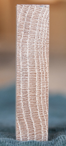
You can see the end result where the router has stopped right at the pencil line. 

Roundover Stopped at Line


 U 
Asymmetrical Routing
Unfortunately, the router bit leaves a little bit of a tail at the end of the cut so the round over does not cleanly end at the line.  Here I have marked the routing with a pencil to make it stand out.  As you can see the tail is asymmetrical and to me looks wrong.  To fix that I will have to wait until I get the banding in place and then come back with a rasp, file and sandpaper to clean up the intersection, all 44 of them.

The good news is that when I got all the routing done the joints at the leg corners were barely visible, even when you know where to look.
Finished Roundover


The banding is next, when I checked the pieces I had rough cut most of them were in good shape.  A couple had bowed a little but not enough to cause a problem when cut into less than 6” pieces.

I decided to start with the bottom banding, no good reason other than they are at the bottom of the leg and I had a fixed edge to line up with.

First I ran all the pieces through the thickness sander this time with a fine (220) grit paper.  That way I will have less final sanding later on.  Next is to cut the pieces to final width.  With that done using the miter saw I cut several pieces 1/8” oversize, mitered 45 degrees on both ends.  I then loosely clamped one on the left side, set the piece to be fitted on top and adjusted the two pieces until they were both in place and aligned with the bottom of the leg.  With both pieces in place I tightened the clamp to securely hold the left piece in place.

Using a .5 mm mechanical pencil I marked the underside of the top piece.  This gets me close to the length of the inside face.
Setup to Mark Banding Piece Length


Since I will be cutting the piece from the front side to minimize splintering I need to transfer the line to the top.  I use a 45-degree steel angle gauge for this.

Transferring Length Mark to Front of Band Piece

Next is to clamp both left and right side pieces in place.  If I had three hands it would really help.  I use a cutoff scrap piece to get them in correct alignment.

Clamping Left & Right Banding Pieces to Leg

The piece I marked earlier gets cut just a tad long then dropped in at the top between the two clamped pieces to check on the fit.  If there is a gap between the back of the piece and the leg, then it is too long.  If it slides back and forth between the miters of the side trim pieces, then it is too short and scrap.  The amount that I trim off when doing the final fitting is really small.  My method is to bring the chop saw down then slide the piece against the body of the blade, raise the saw, start it and make the cut.  What this gives me is a cut equal to the set of the teeth on one side of the blade, in my case that is about 13 thousands of an inch.
Test Fit for Top Banding Piece
When I get close to a final fit I take the piece to the router table and run it through to get the ¼” roundover on the top.  Because the piece has miters on both edges I can’t use the bearing as a guide since there is nothing for it to ride against at the start and end of the cut.  Instead I set the fence up to guide the board.
Router Table Used to Route Roundover on Band

When I get the piece fitted just right I apply glue to the center half of the banding, shoot 4 pin nails to hold it in place then clamp it down.  That’s one down and 31 to go.  I do all four legs this way then let the glue cure for a couple of hours, take off the clamps, rotate the leg, fit another piece and repeat until all four pieces are in place.
Top Band Piece Glued & Clamped in Place
I glue just the center couple of inches because the grain is running one way in the leg and 90 degrees to that in the banding.  This means that as the humidity changes the leg wants to expand/contract one way and the banding the other.  If things are locked together too tight then something is going to give.  Probably the banding would crack or come loose.  By just gluing the center of the banding it reduces the fixed portion of the connection and allows more area of the banding and leg free to move independently.  If I were keeping the table here in the desert climate where it’s dry most the time I would not worry so much.  Remember, the wood was below the minimum detection point of the moisture meter.  However, the table will end up in humid Arkansas so I need to take some extra precautions.

Once the glue has cured there is one last detail to take care of.  I need to route a round over on the vertical corner of the banding where the two pieces meet.  I will use the same size bit I used to round over the corners of the leg for a consistent detail.  The router takes care of 99% of the work but I still need to some finish sanding to blend it all together.  Because the trim pieces are cut sequentially from a single board the grain wraps around the corner pretty well.
Before & After Routing Roundover onto Corner
The top banding follows the same process except both the top and bottom edges have a routed round over.  If you are wondering I did number all the pieces so the grain would wrap around the corners and I would not get them out of order.
Top Band Installation in Progress


Next Up Banding/Leg Intersection & Roughing out Top Pieces

Monday, September 19, 2016

Dining/Game Table - #5 Filler Strips, Ripping Leg Banding & Trim

Filler Pieces in Legs
There are two places where I have to add a filler strip to align the long pieces of the leg.  Both are at the top of the leg with one thin and one thick piece.  I could have designed the piece so they would have not been needed but doing so would have increased the machining difficulty considerably with no gain in strength or appearance.

When I was cutting the leg pieces to size I marked the cutoffs so I knew which piece they came off of.  Now I can go back, retrieve that cutoff and use it to make the thin filler strip.  Since it’s from the same board the grain and color matches very well.  I start by cutting a blank about 7” long so I am not working with such short pieces then rip the filler on the table saw just a little thick.  Next is to use thickness sander to bring it down so it’s just a smidge oversize.  This also removes any table saw marks from the strip. 

To get the length I hold the piece in place and score using a marking knife.  Look just to the left of the knife point and you can see the score line in the wood.  I use the knife because it gives me a score line right at the exact length.  No need to worry about a fat pencil line or if the pencil is sharp enough to get in the corner.   The final cut is made with a miter saw using the score line as a guide.
Marking Knife and Score Line for Filler Strip

To install I apply some glue to the filler strip then use a flat plate vice-grip style clamp to assure the edges are parallel. 
Filler Strip Clamped in Place Ready for Pin Nails

A few pin nails hold the piece in place and a block spreads the clamping pressure to assure a gap free joint.  It did not take very long until I had all the filler strips glued up and set aside to cure.
 
Thin Filler Strips Glued, Clamped and Curing
I use an air powered pin nailer that fires very thin pins to hold the filler strips in place.  The pins are 23 gauge, that’s just about 22 thousandths thick.  They all but disappear in the pores of the oak.  The pins really don’t hold the filler strip in place permanently but act to keep it from shifting until the glue dries.  Think of them as temporary clamps.
Pencil and 23 Gauge, 1/2" Pin Nail

Once the glue cures I remove the clamps and sand the filler strips flat with the adjacent surfaces.  The only place you would be able to see much of a difference is where the ends meet or the end grain joint.  That is not a problem since the top band that wraps the leg covers that joint.  There is a second (thicker) filler strip that goes through almost the same fitting and gluing process as the thin ones.  Only difference is that it fits in a pocket and does not need the pin nails to hold it in place while the glue cures.  Clamping takes care of it just fine.  Here are the before and after views.
Before and After Filler Strip Installation

Earlier on I had cut plywood fillers to plug the bottom of the leg.  I could now run a bead of glue inside the leg and against the earlier blocking I had installed.  Then all that was needed was to push the plug in until it bottomed out against the blocking and clamp it until the glue cured.
 
Leg Bottom Plugs Glued and Clamped in Place
With all that done I could start on the banding that wraps the legs and the trim pieces.  The banding is just under ½” thick and stained the same color as the legs.  The trim is just under ¼” thick and stained a darker accent color, both still to be determined.  We are pretty close but the stain color is not yet finalized.

The oak boards I have are 13/16” of an inch thick.  That means that I can rip the board vertically and get both banding and trim pieces out of one board with no waste.  There is just one tiny little problem, the width of that rip cut and any cleanup to the cut can’t be any more than 1/16” wide.  The only tool I know of that will give me a kerf that narrow is a bandsaw.  Even then it’s going to be interesting in making a 4’ long freehand cut that does not vary.

First is to rough cut the 4’ blanks a bit wide for the banding and trim.  The 4’ length works out to be the banding needed for two legs and is not so long that is will be awkward to rip.  Next I clamp the board in my bench vices then using a pair of marking gauges, one set at ¼” and one set at ½” layout my maximum cut lines. 
Banding and Trim Blank Ready for Layout Lines

Looking at those lines there sure does not seem to be much room between them.
Bandsaw Lines to Cut Between
With the layout done it’s on to the bandsaw.  Here is the setup, on the left is my pivot point and to the right is a magnetic featherboard that keeps pressure on the board helping it keep at 90 degrees to the table. 
Bandsaw Setup

End View of Flat-sawn Blank 
I can’t use a regular fence as a guide for a couple of reasons.  First is blade drift, a tendency for the blade to want to cut at an angle not parallel to the fence and because of the wood.  The wood reason takes some explanation.  The oak I am using is nearly flat-sawn.  That means the growth rings are pretty much parallel to where the bandsaw blade will cut.

An example is as the blade cuts the board the left side of the blade may hit the hard part of the growth ring while the right side of the blade is in the softer wood.  The blade wants to head down the path of least resistance causing it to go off on it’s own.  In this case toward the softer wood or to the right, not necessarily where I want it to go.  That’s why I can be cutting along with the drift set just right getting a nice straight line and then the blade will change direction.  When that happens I need to adjust the angle the board is being fed into the blade by swinging the uncut part of the board one way or the other.  In the end everything worked out fine and I kept the blade between the lines.  A few passes through the thickness sander and I had all the banding and applique pieces I needed for the legs plus the ones needed for the rails.  Here are the pieces stickered and set aside.  I will let them set for a bit so I can see if any of them decide to go all curly-que on me.
 
Banding and Trim Pieces Set  Aside to Check for Stablity

Next Up – Routing the Round Over, Applying the Banding

Sunday, September 4, 2016

Dining/Game Table - #4 Foot Blocking, Glue-up & a Problem

As I had all the legs temporarily clamped up I thought I would take some scrap plywood and see what the banding would look like.  When I cut the banding according to the dimensions on the drawing they looked to be in proper proportion but not quite the right scale (left leg).  Cutting a second set slightly larger (right leg) seemed to be more in scale.  As I said early on the final piece probably would deviate slightly from the original drawing and this is the first instance.
Mock-up of Different Banding Widths

The leg is hollow and I am going to add a ¾” thick piece of plywood at the bottom end for two reasons.  First it should help to reinforce the leg and second it will give me a place to mount the glides I plan on installing.  To provide support for it I am adding some plywood blocking inside.  Here is the setup I put together so I would not have to measure everything.  First, I clamped a straight piece to the bench edge, then used a scrap piece of plywood the same thickness at the base to get the proper setback for the blocking.  The blocking that gets attached to the rabbited pieces is slightly narrower than the inside face so that’s easy to locate, just center, glue and nail in place. 
 
Jig to Install Blocking in Legs
The filler pieces need room for the rabbit lip and the blocking on the rabbited pieces.  To set them correctly I cut a spacer and used it to get them in the right place.  Taking a little time to make a spacer like this sure speeds things up and helps prevent miss-alignment do to measuring errors.
Spacer for Setting Blocking

Here are the legs pieces with the blocking installed and a closer view of how three sides will look assembled with the bottom in place.
 
Left - Ready to Assemble, Right - Test of Fit

First Leg Glued & Clamped
Now it was time to glue up the first leg.  I applied glue to the rabbits, put the four pieces together making sure they are in the right order.  I don’t want to end up with three left legs and one right one.  From there I put on an armload of clamps and let it cure.

Normally I clean up any excess glue squeeze-out, check the joints, and let the glue cure.  This time I tried something a little different.  I left the glue squeeze-out until it was rubbery then cut it off with a sharp chisel.  It did not work out as well as I had hoped.  Yes, the glue came off easily but because the bead of glue had squeezed out of the joint I could not see to check on how tight the glue joints were.  Most of them came out just fine but in a few places they were not completely closed up negating all the work done to assure they would be tight as could be.  To say I was not happy is a big understatement.  All I know for sure is that I am NOT going to do the glue up on the rest of the legs that way.
#@!**& Gap in Leg Joint

The next leg I glued up the way I usually do cleaning the glue off right after clamping.  Also, this time while I was at it I added a few more clamps.  The result was much better – no gaps :)

2nd Leg Glue-up 

To fix the gap if this were one of my typical (unstained) projects I would mix a little of the sawdust with my finish (lacquer) then fill the gap and once the whole piece is sprayed with finish the gap would disappear.  However, because this piece is going to get a rather dark stain that won’t work.  This left me with two options, try and use some stainable filler or wait until the project is completely done and use a color matched filler. 
Saw Kerf for Filler Test

The possibility of finding a color matched filler for a custom made stain mix did not seem likely.  Also, the gap will be right at the point where the round over that goes on the leg ends and I would like to have that edge backed up by something solid.  That said, I have never used stainable filler and did not know how well it worked.  A trip to the local big box store provided a couple different options.  After reading the labels I decided to go with one whose ingredients seemed to provide for some ability to absorb stain.

The only way to know how well it would work would be to do some testing.  I started by taking cutoffs from the legs then using a fine back saw cut a narrow kerf to represent the gap.  Even using a thin back saw the test cut is quite a bit wider than the gap in the leg. 

I finally decided to test three different materials.  First is the stainable filler, second a glue/oak sawdust mix and last a water based putty I had.  I applied the stainable filler per instructions using a putty knife.  The glue/sawdust was next.  For it I mixed some thinned yellow glue with oak sawdust and applied it with the putty knife also.  The water putty was last and I simply filled the kerf using my finger.  After curing and sanding the stainable filler was a light tan as was the water based putty.  However, the glue/oak mix was black.   At first it did not register why but then I remembered that when you have a water based glue as I did and oak and an iron material like a putty knife (or clamp) the tannin in the oak reacts with the iron resulting in a black stain.  Mystery solved so I redid the test using a piece of oak to mix the glue/sawdust and pack it in the kerf.  When it dried it came out fine.  Applying stain and a quick shellac finish to each piece gave me a representative example of how they would look.  The results surprised me as I had thought that each of the samples would take the stain differently but in this instance that was not the case.  They all look to be just about the same.  The stain I am using is really a dye with alcohol as a carrier.  Perhaps if I had used a water based or petroleum based stain the results would be different.  I did one additional test before I decided which to use.  I put a small lump of the filler and some of the putty out to dry then did a crush test to see which help up better.  The water based putty was my choice as it was hard but not brittle which should help as the wood changes size with the humidity changes.
Stainable Filler & Water Putty Test Samples


Next Up – Filler Strips, Ripping Leg Banding & Trim