Router Plane

Monday, February 28, 2022

Wood Egg - #1 The Beginning, a Fixture & Shadow Turning Setup

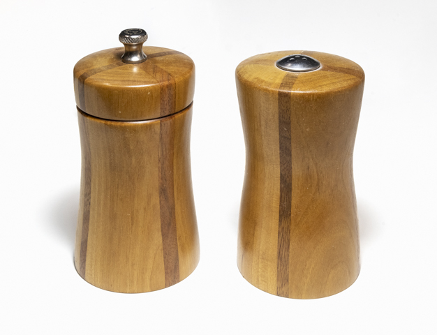
In the past I have turned a variety of different sized spheres in numerous different woods including some laminated ones.  They don’t use much material and are a fun little lathe project.  For other purposes I have also turned some elliptical pieces, mostly as handles.  However, on the couple occasions that I attempted to turn an egg shape the results looked pretty bad.  Actually, they were closer to a football than an egg or maybe what Picasso or Dali would have done.  Not too long ago I saw a demonstration on how to turn an egg using a shadow method.  Since that was a technique, I had never tried I couldn’t resist giving it a try.

Like a lot of other of my projects a couple of things need to be made before the egg could be turned.  The first is a small fixture to hold a real hard-boiled egg that will be used as the pattern.  Using an old glued up scrap block a piece was cut to make the blank for the fixture.

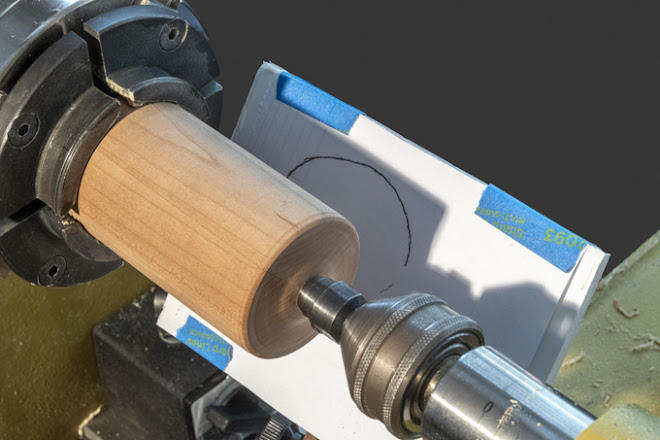
First the blank is mounted between centers on the lathe and turned round as shown in the top photo.  Next the blank is lightly mounted in the 4-jaw chuck then the point of the live center in the tail stock is inserted in its original location on the end of the blank.  This aligns the center line of the blank with the long axis of the lathe assuring the blank runs true as in the bottom photo.

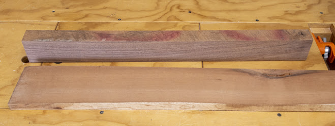
Not knowing for sure what size, the fixture needed to be the first attempt in the upper left ended up too long for the wood blank that will be used to make the egg.  The second candidate in the upper right was better but still too long.  The third try gave me a compromise between work space around the chuck when turning the egg and being able to use the blank I plan on using.  At least it looks that way. 

To make a wood egg a real egg is used as a pattern.  It is hard boiled to prevent a mess just in case a there is a problem.  Here it is set in the just made fixture at the left end.  There should be enough room between the egg and the headstock for me to do the turning.  The live center at the tailstock end has the center point in the black live center insert removed so it does not punch a hole in the egg.  

With a way worked out to hold the egg in place next is to make a holder for a sheet of paper so the shadow of the egg can be drawn on it.  Below, the top photos show the front and back of the finished shadow board holder.  The articulating arm is from my dial indicator set.  The paper is attached to a small piece of foam core stuck to the leftover piece of wood used to make the dowels for the Sanding Blocks.  All it required was the end to be turned to a slight taper to fit in the articulating arm’s mounting hole.  That turning setup is shown in the bottom photo.  Bear with me for a minute as the actual method for turning will become clear soon. 

The setup for making a pattern is shown in the left photo below.  The red arrow points toward where the egg is in the lathe.  Also shown on the right of the same photo is the light that will cast the shadow of the egg onto the paper.  The light needs to be as small a source as possible.  Here a halogen work light with a focusing reflector is used.  A regular frosted light bulb does not work very well as it gives a too diffused light source.  Better would be a single point LED fixture.  Locating the light properly is important as it needs to be set so it’s 90 degrees to the face of the shadow board.   The photo on the right shows the egg set in place and ready to go albeit with the light turned off.  Below the egg you can just see the articulating arm’s magnetic base on the lathe’s way.

In the top photo below, you can see the shadow when the halogen light is turned on and where the shadow line has been traced with a pencil.  The bottom photo is the same except the halogen light has been turned off.  Now I have a pattern to turn to.

Here are a couple more photos of how the pattern looks from a straighter on view.  These photos couldn’t have been taken with the halogen light on since the camera would have blocked the light that makes the egg’s shadow.

Next the already turned round blank gets mounted back in the 4-jaw chuck.  The top photo shows the blank lightly clamped in the chuck and the tail stock on the right end ready to be run in tight to the cone.  This cone will center the blank in the lathe.  The bottom photo shows the tailstock run in.  Once centered the chuck gets tightened down to securely hold the blank.

With everything in place, the halogen light is turned on.  The photo shows the shadow cast by the blank onto the shadow board.  All that’s needed now is to turn away the blank so the shadow aligns with the pattern and what’s left is the egg shape.

Next Up – Completing the Turning, Finishing & a Problem

Monday, February 21, 2022

Pepper Grinder - #3 Final Turning, Finishing & Assembly

The slight transitioning curve to the rounded corner that blends in with the sides starts by flipping the piece end for end since the top is at the chuck end and I need more room to safely work than is available.  It doesn’t take a lot to make the transition pleasing to look at and feel good.  The taper itself is probably not much over 1/16” and the rounded corner is about a 1/8” radius.  Small details, but it makes a big difference when held.  This photo shows the turning completed and all but the final 400 grit sanding done.  That sanding is done by hand using the 400 grit paper on the sides but not done with the lathe on and the piece rotating.  The lathe is off and the sanding is done following the grain of the wood which runs from top to bottom of the piece.  This gets rid of the fine circular scratches left by sanding when the lathe is running.

A final assembly is done to check and make sure everything fits together without any problems.  As everything checked out finishing is next.

No dye or stains are used in the finishing, only a clear finish.  For good protection three coats of lacquer is applied by spraying using my airbrush.  Here is the standard setup with the brush, regulator, respirator and gloves.  The two larger plastic bottles at the right have lacquer and thinner in them.   The gallon cans of lacquer and thinner are out of the photo.

To spray the piece a scrap of 2x4 is turned to a taper so it fits snugly inside.  Holding the 2x4 piece in one hand and the airbrush in the other allowed me to turn the piece all directions and spray all the outside surfaces at once.  Once sprayed it is clamped in the bench vice and left to dry.  The next day it gets wet sanded with a 2,400 grit pad and another coat sprayed on.  After drying overnight, it gets wet sanded again and the final third coat is applied.  It is then left to cure for several days to harden before wet sanding with an 8,000 grit pad to remove any little bits of dust and the like on the finish.

This is the bottom of the pepper grinder showing the mechanism along with a drawing showing how the mechanism goes together.  The two holes in the bottom plate get a couple of very small screws which holds the mechanism in the grinder. 

Because the screws are so small, I was worried that if I tried to just screw them in without a pilot hole, they would get twisted off or split the wood since they are very close to the inside edge.  Neither of which is a desirable outcome.  My smallest regular drill is 1/16” (.0625”) in diameter which is right at the diameter of the screws so that wouldn’t work.  What I do have is a set of 40 orifice drills I inherited from my father that range from size #80 (.0135”) to #40 (.098”).  The one that gave me the right size pilot hole is a #57 drill (.043”).  It along with the screws and a ruler is shown below.

To reduce the chance of the screws splitting the wood the holes are drilled at an angle away from the hollow center.  This is what the pilot holes look like drilled.

After letting the lacquer harden and gas off the mechanism is installed using the two itty-bitty screws to hold it in place.  To help prevent twisting the screws off during the installation they get a thin coating of wax to act as a lubricant.

Here is a photo of the original salt and pepper set along with the new pepper grinder.  After finishing it we decided the originals are going to be kept on the dining room table for use there while the new pepper grinder will be kept in the kitchen to be used when larger amounts of freshly ground pepper are need for cooking.

After filling it with peppercorns I gave it a test run and wow does work.  It grinds pepper at least four times as fast as the old one and a lot easier plus it's a lot easier on my wrist when trying to grind a quantity for recipes.  This is certainly worth the $10 or so the hardware cost.

Monday, February 14, 2022

Pepper Grinder - #2 Drilling & Turning to Shape


The information from the manufacture for drilling the blank to provide room for the hardware and peppercorns is in the left drawing below.  Since my finished pepper grinder height is taller than the one shown in the drawing some revisions need to be made.  Also, two of the bits required, the 1 1/16” and 1 3/16” diameter are sizes that I don’t have.  The right shows what will be drilled to accommodate what I do have along with the finished diameter understanding that some additional other work will be required to get to the required 1 1/16” and 1 3/16” diameters shown.

Setting the blank up to drill requires the lathe’s drive center to be removed and a 4-jaw chuck put on.  The bottom of the pepper grinder blank gets set in the chuck and lightly snugged down.  To make sure the top is centered the tail stock is brought up and the live center’s point is set in the same point as when the blank was held between centers.  This assures the center line of the blank is in the same position as it was initially turned round.  With that done a 1 ½” Fostner bit is put in the drill chuck and a 1/8” deep hole is drilled.  Here all the above has been done.

Drilling the center hole is next.  While it will eventually go all the way through for now it gets drilled just short of coming through.  That’s so I can use the center mark on that end to align the blank when it gets flipped end for end.  The red arrow points to a light pencil line on the bit to mark the depth of the hole.  I start with a ¾” diameter bit to hog out most of the material as shown here.

Next a 1 1/8” hole gets drilled about 1” deep.  The reason for that will get explained later.  Here the bit is just getting going.

With the drilling done at the top the blank gets reversed putting the undrilled part at the bottom.  There are three different diameters for the bottom.  First, is the 1 ½” diameter hole that gets drilled deeper than the original plans since the pepper grinder is taller than the one shown in the supplied plans.  Second is one 1/8” deep and 1 3/16” in diameter.  Since the closest bit I have to that size is 1 1/8” a parting tool is used to cut it the 1/32” wider on the side for a total 1/16” wider.  Last is the 1 1/16” hole the grinding mechanism fits in and the closest bit I have is 1”.  Because this hole is deeper into the body of the blank and smaller it can’t be enlarged using the parting tool.  After trying several methods that didn’t work, I settled on using the die grinder with a carbide burr.  This is a pneumatic power tool that runs at about 20,000 RPM’s and just glides through wood. 

If I tried to using it under power with the burr to remove 1/32” of material from the side of the hole (1/16” total diameter) it would be like trying to do surgery with a chain saw.  What did work was to hold the tool in place turn the lathe on low speed and just hold the burr against the side of the hole, like a file.

This process worked fine as the material removal could be easily controlled.  Once the correct size was attained a little sanding is done to smooth the surface and I was finished.  Here is the end view of the blank all drilled out.  Now it would have been a lot easier to make with the right sized bits and if I was going to make several of these I would but I didn’t feel like buying the bits for a one-off use.

With all the drilling done the grinding hardware gets installed for a test fit.  Everything fit and the crank worked great.  Next is to chuck the blank up and turn the profile so it matches the existing salt and pepper shakers.

Up to now the blank has been held in the chuck using jaws that grab the outside of it.  Now to turn the exterior of the piece to its final shape the chuck needs to grip from the inside.  To do this requires changing the jaws from what’s on the chuck body to a different set.  Below on the left is the setup that has been used so far.  It’s minimum gripping size from the inside is 2 3/8” way too big to use.  The middle is the blank as it is now and on the right is after the jaws have been changed out.  The minimum inside gripping size is 1 1/16” which is 1/16” smaller than the 1 1/8” hole drilled in the top of the blank.  As the bottom has a 1 ½” diameter hole it could be used but I will be using the top 1 1/8” hole because the walls are thicker and will provide more strength when the chuck is expanded to hold the blank in place.  What I really don’t want to happen is to apply too much outward pressure and split the blank apart.

In the top photo the blank is mounted in the lathe ready to turn.  The bottom photo shows the outer edges and the center turned down to just over their final diameter.  The white lines are for guidance while the arc is being turned to give the piece a narrow waist so it feels better in hand.

The tapering is not straight but a gradual curve or hourglass shape to the waist.  This is done by working from both sides toward the center to make sure there is good symmetry between the top and bottom.

Once satisfied with the hourglass shape the piece is sanded up through 400 grit.  It’s not done as I do have a little more turning to do.  Right now, the top and bottom are flat and square to the now gracefully curved sides.  Once I break the bottom edge it will be done but the transition from the top to the side is too abrupt.  What’s needed is for the top to have a slight curve transitioning to a gently rounded corner that blends in with the sides. 

Next Up – Final Turning, Finishing & Assembly

Monday, February 7, 2022

Pepper Grinder - #1 The Beginning, Glue-up & Rough Turning

Sometime prior to 2002 I made a laminated walnut and cherry salt and pepper set on the lathe that has been in use ever since.  There has been only one problem with the set and that is with the pepper grinder.  It works fine for individual use but when grinding a lot for cooking my wrist gets tired.  I tried modifying another grinder but it was not much better so we continued to use it and complain every time a lot had to be ground. 

That all recently changed when looking through a woodturning catalog I came across a set of good-looking stainless steel pepper grinding hardware.  It was only about $10 so I ordered it along with some other items that I needed.  Here is the hardware and the catalog photo.

The new grinder could have been made out of a laminated block matching the originals.  It would have been close because I still have a piece of the walnut.  However, the new cherry would have never matched the natural darkening of the 20+ year old wood.  What I decided to do was match the shape of the old set but reverse the woods.  The original pieces have a cherry body with walnut accents.  For this piece I will reverse that.  Here is the stock that includes the part of the original walnut plank.

To make the turning blank will require three different glue-ups.  The first two are identical, two thick walnut pieces with a thinner piece of cherry sandwiched between them.  Here they are glued and clamped up.  The 6-mil polyethylene plastic sheet is to keep the clamps from getting glued to the wood and the blank from getting glued to the workbench.

After an overnight cure the clamps are removed to reveal the glued-up blocks.  Here is one of them and you can see where the dried glue got squeezed out.  Because of the plastic sheet it could not get cleaned up while being clamped.  The paint/glue scraper will be used to remove the excess glue.

The glue needs to be removed from both sides before the piece gets run through the thickness sander. That’s so the glue doesn’t get transferred to the sanding drum gumming it up which in turn can cause a burn mark in the wood.  Anyway after a few passes all the glue is removed and the piece can be run thought the sander to remove any scraper marks and make sure the surface is flat.

Next the two glued-up blocks get glued together with a cherry spacer between them.  Here it is all glued and clamped up.

Once the glue cures the clamps are removed and any glue gets scraped off.  Unfortunately, when scraping the excess glue off I got a little carried away and slightly rounded a couple of the edges a little.  Because this block is going to get turned round it could have been left that way and not caused a problem.  However, only about a third of the block is needed for the pepper grinder and the rest will be set aside for some future unknown project.  Because of that I wanted the block to be square and flat so a flat reference surface is needed.  To get that surface a shim consisting of a strip of playing card and a single layer of masking tape is put on the low side to bring it up level.  That is shown in the photo below.  In use the tape goes down on the feed belt and opposite side gets flattened by the sanding drum.  When it’s flat the shim is removed and that face of the block gets flattened.  As you can see there is knot on one corner of the block.  It probably won’t be a problem as I think it will be in an area that will be cut away when turned to a cylinder.  At least that’s the plan.

Laying out the cylinder and how the knot will intersect that is next.  The top photo shows the edges of the knot transferred to the top and how they would intersect with the cylinder.  The bottom is a closer view of that intersection.  Since the drawn cylinder is a little larger than the diameter of the finished pepper grinder It looks like the knot will get cut away.

Cutting off the pepper grinder blank is next.  The rest of the block on the left will be stored away with my other blocks for something else.  Maybe another salt/pepper set as a gift???

Using the bandsaw to rough out the cylinder is next.  When making this cut, I noticed a bit of burning which when making tight curves is not uncommon but here it’s more than usual.  Also, more pressure was needed to make the cut than normal.  This blade has cut a lot of material in the past two years including ripping a couple pieces with nails that were hidden damaging the blade.  All in all it’s time to retire that blade and put on a new one.  On the lower left of the photo there are two cutoffs laying down.  They are from the corner where the knot was and got completely cut away so that’s not going to be a problem.

With the blank mounted between centers in the lathe the turning can start using a roughing gouge.

The rough turning down to a smooth cylinder went well as both walnut and cherry turns really nice.  However, when I stopped the lathe to check on the diameter I discovered a little crack on one edge of the blank circled in red in the top photo.  Fortunately, it didn’t look very deep and a little more turning cut it away so it ended up not being a problem but I have had cracks like that show up and end up being a real problem.  With that concern out of the way I finished up the rough turning taking the blank down to a smooth consistent diameter a little oversize so the drilling for the grinder’s hardware could start.

Next Up – Drilling & Turning to Shape