Router Plane

Monday, September 30, 2019

FLW Cabinet - #19 Moving Shelf Holes & Assembling the Case

Having to move a row of 14 holes down by 1/8” is not exactly something I was looking forward to however it has to be done.  Unfortunately, so far in woodworking there is not a “hole relocator” tool.  The fix is to fill the holes and re-drill them in the proper spot, easier said than done.

First, is to sort through my pile of cutoffs and scraps looking for a piece whose color and grain closely matched the plywood.  Once found I used a plug cutting bit to make the plugs as shown here.  The plugs are cut about an 1/8” shy of going all the way through the blank.


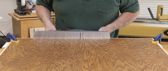
Second, is to set up the bandsaw to make a cut that will free the plugs from the blank and properly size their length. 
Here they are all cut loose.  In case some of the plugs had a flaw, I had drilled a few extra.

Fourth, is to glue the plugs into the incorrectly located holes.  That’s done by selecting a plug whose grain is close to the grain of the plywood then using a small nail spread some glue into the hole followed by inserting the plug and tapping it down solid with a rubber mallet.  Here’s the setup for that.  The glue is put in the hole because if you put it on the plug as it’s driven in the top edge of the hole scrapes most of the glue off and you end up with a ring of glue that has to be removed from around the plug.  Note that the plugs stand about 1/8” proud of the surface of the plywood.

Fifth, is to get the plugs flush with the surface of the plywood.  That’s accomplished in two steps starting by cutting the plug close to the plywood.  For that I use a very thin Japanese pull saw whose teeth have no “set” and a piece of paper acting like a spacer.  A saw blade’s “set” is the distance the saw tooth is bent away from the saw blade.  It is this set that will scratch the surface of the plywood when trying to cut the plug flush.  That’s where the piece of paper comes in as it provides a very thin layer of protection to the plywood veneer.  The last little bit needed to bring the plug flush is done with a card scraper.  Below shows the uncut plug with the paper spacer and right at the tip of the saw a completed plug flush with the plywood.

After all the plugs are flush with the plywood, I can set up the jig then use the plunge router to re-cut the holes in the proper place.  Here are a couple of completed ones. 

Next is to start assembling the case itself which includes putting the sides, back, front, bottom and sub-top together.  That said there is a little final detail work to be done on the front and back.  First, is to do a bit of drilling.  On the legs the intermediate pairs of square holes already have a counter sunk hole drilled at the bottom of the peg hole for the screw that will get run into the side.  However, the top and bottom where the leg/rail mortise and tenon join does not have it.  Here is a section showing what I mean.  The gray is the leg while the tan is the rail tenon.  The area in white is the counter sunk and pilot hole for the screw.

I need to mark the center of the square peg hole accurately as I want the screw centered in the plywood side to minimize the chance of it splitting when screwed together.  The easy way is to take the mortising chisel set it in the peg hole and whack the drill with a wooden mallet which marks the center. 

Using the marked center point I start by drilling a small guide hole.  To keep the drill plumb a square is used.  After that the counter sink is drilled and then the appropriately sized pilot hole.

Attaching the side comes next.  Using clamps to hold the side roughly in place a small jig is used to locate the side so it is centered on the peg hole.  Here one side is done with the other clamped in place ready for the screws to be installed.


After attaching both sides the next item is to attach a ledger strip that will support and provide attachment points for the bottom.  Here it’s shown installed but with the clamps still in place.  The four spaced plywood blocks on the top are scraps temporarily screwed up through the ledger that match the bottom in thickness.  They are used to set the ledger so the bottom will be flush with the back rail.  Because plywood has some variance in thickness the ledger is just screwed on and not glued in place.  Also, the mounting holes are a little oversize so when the actual bottom is installed, I will have some room for adjustment.  One thing I did not anticipate was how close the bottom of ledger is to the floor.  With so little room I had to use a 90-degree attachment on the drill to remove the screws holding the temporary spacers in place.
 
Once the sides and back are together the front gets installed next.  This time I put the ledger on before screwing the front in place which made it a lot easier.  Installing the front follows the same process as the back.

For the basic case that leaves only two pieces, the sub-top and the bottom.  As both have been cut to width I just need to measure and cut them to length using the crosscut sled.  For now, the bottom is just dropped into place to help square up the cabinet.

After cutting the sub-top to length and before it is installed, I have to drill the pocket holes on the top face for anchoring it in place.  Here it is in the jig set up for drilling the last hole.  If you are wondering the chalk mark is where there is a flaw in the plywood.

The two key items used with pocket holes is the step drill shown on the left and the pan head screws shown on the right.

After screwing in the sub-top (top photo) I laid the cabinet down on its back and the bottom is attached from the underside (bottom photo).


Standing it back up here is what it looks like.  One down and one to go.

Next up – Plywood Void, Door Spacer, Fitting Door & Mounting Hinges

Monday, September 23, 2019

FLW Cabinet - #18 Side Panel Preparation & a Problem

Now that the front and back frames are done, I can measure and cut the sides to their final length.  The bottom will get cut to length later once the sides are in-place.  Both the sides and the bottom have already been cut to final width so that’s done.  Since the sides are about 76” long a crosscut sled is used to make the cut.  Here is what that setup looks like.

Before the sides can be screwed to the front and back assemblies, they need to have holes for the shelf pins drilled.  To make the ¼” shelf pin holes I use the jig below which has precisely spaced holes.  The peg holes can be drilled with either a self-centering drill bit in a hand drill or by using a plunge router with a 3/8” bushing and ¼” router bit.  In the past the self-centering bit in a hand drill has always been used.  However, if you go too fast sometimes the bit tears the thin veneer when starting the hole leaving a bit of a rough edge.  So, to see if the router worked better, I decided to try it on a test piece. 

I will use my small router because the hole is small and I don’t need the power of the large one.  Also, it weighs a lot less which is a plus.  First is to remove the large opening plate on the plunge base assembly and replace it with a plate designed to take a bushing.  Here is the router with the plate designed for the bushing and the bushing.

However, before installing the bushing I checked to see how it fit in the jig.  The diameter fit perfectly but the bushing was too long and protruded out beyond the base of the jig by about 1/16”.  So, the bushing gets removed from the base plate and it's off to the grinder to remove the excess.  Right off the grinder I was left with a rough edge that was not completely true or square.  That’s fixed by mounting the bushing in the lathe then using a file to even up and round over the rough edge as seen here.

There is a little room for adjustment of the router base plate so the bushing can be centered on the router shaft.  To do that this cone shaped brass piece having a ¼” shaft gets mounted in the router then the base is run up snug against the cone centering the base.  All that’s needed then is to tighten the screws.  Now when I mount the bit in the router it will be centered in the bushing opening.

The router bit is installed next.  After that the router is turned upside down, the jig set on the bushing which now is just a tiny bit below the surface of the jig and the depth of cut is set on the router.  Here is all that done.


After clamping the jig and the test piece down I was ready to make a test hole.  The green tape blocks off some of the holes as I am only going to use every third one. That puts the shelf spacing at about 4”.  Without the green tape I can guarantee that I would put a hole where it should not be.  Process is to turn router on then on the back side of the router out of sight a release lever is pushed which unlocks the plunge mechanism and you just push down.  The bushing makes sure the hole is in the right place and the stop controls the depth.  Easy.

Below are the results of the testing.  The hole on the left (D) is made with the self-centering drill and you can see how the edge is a little rough.  Part of that can be taken care of with some light sanding but the edge is still going to be a little rough.  The center hole (R1) is done with the router and the edge is a lot cleaner.  However, I made the plunge a little too fast and burnt the edge of the cut hence the brown ring.  Slowing down the plunge on the right hole (R2) gives me just what I wanted a nice clean hole.

To finish up the test I pulled out a couple of ¼” shelf pins and they fit in the drilled hole but not in either of the plunge routed ones.  What the heck is going on here?  A little measuring with the digital caliper told me what the problem was but not why.  The drilled hole is about a hundredth of an inch over ¼” while the plunge routed ones are a slightly a bit more than a hundredth of in inch less than ¼”.  The shelf pins measure about .001” over ¼” and just won’t fit into the plunge routed ones.  After some thought the why came to me.  The carbide bit I am using is probably 35 to 40 years old and gets sharpened as needed which over that many years adds up to a lot of sharpening.  I use a diamond hone to sharpen it and over time I must have removed enough carbide to make it cut a hundredth of an inch undersize. 

A trip to the local big box store got me a new bit.  I had considered a solid carbide spiral up-cut bit but I can’t sharpen it so instead went with a straight solid carbide bit that I can sharpen.  Using the new bit, I made another test hole and it worked just fine.  The shelf pin fit flawlessly.  Setting the jig in place I am ready to start making holes.


When you get to the end of the jig it’s moved down the board and a pin locks it in place allowing a continuation of the spacing.  The white pin at the left end of the jig is the registration pin.

That process is repeated until you get to the last hole then repeated on the other side ending up with a piece that looks like this.  28 holes done and 84 to go.

The second side went well with no problems.  However, after completing the third side as I was doing a double check on the hole spacing a problem emerged.  For whatever reason and I still do not know why on the second set of holes the first one got off by 1/8”.  Since all the holes are registered from the first one all 14 holes in that line are off and that’s a real problem.  That’s because unless all the holes are in the same plane the shelf will not set flat and will rock.  The fourth side went without a problem.  So now I have to correct this glitch by moving the row of 14 holes 1/8”.  Not something I had planned on doing and that’s where I start in the next post.

Next up – Moving Shelf Holes & Assembling the Case

Monday, September 16, 2019

FLW Cabinet - #17 Faux Tenons, Staining Back & Leg/Rail/Back Glue-up

After letting the front frame glue-up cure overnight the clamps are removed and finish sanding can begin starting with 120 grit and ending up with 220. 

Back in post #14 Faux Tenons, Side Spacers & the Back I made and fitted the faux tenons that would go through the legs.  Now it’s time to do a final check and complete the work on them.  That starts with making sure there has been no change in their required length after the frame has been glued together.  With that checked out the distance they will be exposed is marked using a marking knife as shown below.  I need to know where the edge meets the face of the leg so I can soften the faux tenon edge.

Removing the piece in the left photo you can see the cut left by the knife.  That gives me the limit of the exposed edge which is then very softly rounded to get rid of the sharp edge.  The right photo shows an edge on view where the left edge has not been rounded but the right side one has.  It’s pretty subtle looking but that small bit of rounding makes quite a difference when you feel the edge.

After the second edge is done the piece is put back in the mortise to check and see if the rounding needs any more work.  Here is what the finished faux tenon looks like dry fitted in place.

In the last post I talked about staining the backs before assembly to eliminate any exposure of unstained oak should any of the material shrink.  However, to make sure there is a good glue joint when the panel is fitted in the groove in legs and rails that part of the panel needs to not have any stain.  If it was a dye using alcohol as a carrier then I would not worry but this is an oil-based stain so I think it would be a good idea to take some precautions.  The simple fix is to use blue painter’s tape and mask off the edge, apply the stain then strip off the tape.  Here is what the back looks like with the tape in place before the stain is applied.

Following the edge taping the first coat of a golden oak stain is applied and the result is on the left.  The following day a walnut gel stain is applied to add some contrast to the grain and add a little more color to the field.  That’s shown on the right piece.


The next day the tape is removed and the plywood is ready for glue-up with the legs and rails to form the back panel.

A test fit with the plywood, legs and rail is next.  Unfortunately, when I got all the pieces together and clamped in place, I could not pull the assembly square.  No matter what adjustment was made the piece just would not square up.  Using a framing square showed it was really close but when measuring the diagonals, it was not close enough.  When checking the plywood panel, I found it was out of square just a tad but not enough to cause the problem.  In addition, the plywood panel had been sized to provide a gap of about 1/16” so when assembled there would be space in the grooves in the leg and rails for some adjustment just in case.  After a couple of very frustrating hours I finally found the problem.  Evidently when calculating the size of the plywood panel I got off ending up leaving no adjustment gap at the top and bottom of the panel.  If you are going to have a panel sizing problem having an oversized one is way better than being too small.  All that has to be done is set the fence on the table saw for the proper width and run the piece through.  However, the panel is a little over 72” tall and the widest cut I can make on my table saw is a bit over 50”.  Also, since only 1/16” needs to be removed from each end I can’t set the fence to take that much off and keep the rest since the blade removes 1/8”.  My solution is to clamp the panel to the workbench, then using a marking gauge cut a line 1/16” from the end.  Here is what the scribe looks like along with the mark I need to cut to.  Note that the marking gauge is similar to others I have used except this one has a curved knife to make the mark. 

With a mark made showing how much I needed to take off I could then use the big hand plane to cut back to the line.  That’s followed by using the block plane to put a small bevel back on the panel edge which makes assembly easier.  This time when I did the test assembly everything went together fine and it could be easily brought into square.  With the problem resolved I called it quits for the day and my wife and I went out for pizza.

The next day the pieces were unclamped, dissembled, glue applied to the tenons and the panel grooves, all 5 pieces put back together for the umpteenth time then clamped, squared and any glue squeeze out removed.  Fortunately, everything went well so the back will sit until tomorrow when I remove the clamps and go through the whole process with the other back.  Hopefully, it won’t be as much of a problem.

After the glue has cured overnight the clamps are removed, the assembly set aside and the test fit is done for the other back assembly.  This one went together much easier than the first one and squared up on the first attempt.  With that hurdle out of the way it’s fairly straightforward to go through the same gluing, clamping and squaring progression as with the first one.  Here is what it looks like completed and ready to let the glue cure overnight.

The next day all the clamps are removed then the legs and rails of both backs are sanded up through my final grit of 220.  That said before staining I will lightly hit the surfaces again so everything is a nice and clean.  In fact, surfaces of a different roughness can take the stain differently.  That’s one reason I sanded the legs after scraping them to get that consistent surface.  Sanding is not one of my favorite things but it is critical to getting a good finish so I break it up and work on it as I go rather than waiting until the end to do it all.  No photo here as an un-sanded piece pretty much looks the same as a sanded one.

Next up – Side Panel Preparation & a Problem

Monday, September 9, 2019

FLW Cabinet - #16 Making the Side Spacers, More Stain & Front Frame Glue-up

Once the decision to use a radius on the side spacers, legs and rails work could progress on completing those items.  I decided to work on the side spacers first.  Previously they were flattened using 100 grit sandpaper on the thickness sander.  Now using 220 grit sandpaper they are run through it again to get a good smooth surface.

Since there are three different patterns between the 16 pieces needed making templates is first.  I followed a similar procedure as done with the rails in Post #13.  A one ended pattern is used to drawn matching profiles on one of the spacer blanks.  

With the profile drawn on the template cutting can begin.  Since the straight cuts for most of the spacers are on the ends, they can be cut on the table saw.  Here is the setup; the fence is set to cut the correct width and a stop block is set to keep from cutting too far into the blank. 

Note that the blade is a lot higher than normal.  That’s so when the stopped cut is made the end of the cut is closer to 90 degrees.  In the two renderings below the bottom one shows what I am after.

The curves on these pieces are quite a bit smaller than on the bottom cabinet rails so to improve the quality when rough cutting them out I changed the bandsaw blade.  Typically, I keep a ½” wide, 3 tooth per inch blade on it but here changed it to one that’s ¼” wide with 16 teeth per inch.  The ¼” blade will allow for tighter turning of the blade.

After rough cutting the curves the blank looks like this. 

From there it’s smoothed out on the oscillating drum sander followed by hand sanding all the edges.  This is one of the two templates I will make.  Earlier I said that there are three patterns which is correct but only two templates are needed since one pattern a partial of this one.

The actual production of the side spacer pieces is:
  1. Tracing the template on a blank.
  2. Cutting the straight sections on the table saw, and the curved sections on the bandsaw. 
  3. Clean up bandsawn curves on oscillating drum sander to prevent grabbing with router bit.
  4. Using double faced tape affix template to roughed out blank.
  5. With a bottom bearing template cutting bit in the router table trim the blank to match template.
  6. Hand sand all edges.
Below the top image shows the template, blank and the bottom bearing bit ready to go.  The bottom photo is after routing.  One down and 14 to go.

Here in the top photo are the stacks of the three types of side spacers all cut, sanded and ready to have the small radius put on the appropriate edges.  It took a day and a half to take them from a blank to this point.  There was a lot of time spent hand sanding to get a smooth flowing surface on the curved edges.  The top spacers get only the bottom edge radiused while all the others get both top and bottom edges radiused.  The bottom photo has the edges marked for the legs and rails that will need to be radiused.

On the side spacers and the front/back rails the radius will be put on with a 1/16” radius bit in the router table.  Here is the setup and a before-after photo of the completed edge.

To apply the radius to the legs a 1/16” radius bit in a hand held router is used.  Trying to route the long legs on the router table is awkward and a lot easier using the small hand held router.  This is what that setup looks like.  It’s using a little bit different equipment but gets the same radiused edge result.

Finally, at long last the legs and rails finished.  The side spacers just need a final trim to length and they will be done too.  Here they are set aside for a little bit but first I want revisit the stain color.

In looking at the selected stained oak sample (bottom pieces with pegs) I thought it might look better slightly darker and with a little more definition in the grain pores.  First, I tried rubbing in some walnut gel stain after the clear topcoat had been applied and that did a little to the pores but nothing to the rest of the sample.  Next I tried applying the gel stain after the first coat of stain and before any clear finish had been applied (top pieces).  I like that a lot better so it’s the stain mix I will be using.  

At this point the majority of the parts for the case have been cut.  The side spacers need a trim to their final length plus there are some hinge mounts to make along with, shelf edging, fitting the tops, handles to make and a whole lot of pegs needed so not everything is done but enough to start thinking about the order the case is going together.  Now is the part where the instructions say, “Some assembly required.”

I am going to start by gluing up the front legs and rails.  That will give me some practice before I do the back legs and rails as they have a plywood insert added to the mix.  Here is the test clamp checking one last time to make sure everything fits as it should and that any adjustments to make it square are not a problem.

The glue-up ended up less of a frantic rush as I thought it would be which is always a good thing.  Everything went together just fine and in a timely fashion.  I did have to tweak things a little bit to make the frame absolutely square.  The adjustments are done by clamping the base rail down to the workbench using the two orange “F” clamps as shown below so it’s locked in place.

At the top the bar clamp with the red ends is set so the right side is up against the bench while the left side pushes against the leg.  This allows me to apply a very controlled amount of pressure to rack the assembly until the measuring stick drops into place indicating that the diagonals are identical and things are square. 

The diagonal measuring stick is set during the test fit.  After making the adjustment I check the opposing diagonal to make sure they match, just in case anything slipped between the test and final glue-up.  With everything square and glued up it’s left to set overnight.

Next up – Faux Tenons, Staining Back & Leg/Rail/Back Glue-up