Router Plane

Thursday, May 28, 2020

Wood Body Pinhole Camera - #6 Completing Film Knobs & Starting the Film Boxes

With the axles done I can move back to the knobs.  Now is where the small cone shaped piece at the end of the knob comes into play.  It gets inserted into a live center that has the central pin removed.  The photo below shows the center with the central pin removed.

The axle is friction fit into the roughed-out knob then installed in the chuck mounted on the lathe while the live center is installed in the lath’s tale stock.  In the photo below you can just see the cone peeking out from the end of the knob and the hole in the live center. 

Here you can see how they come together.  The cone inserted into the live center will keep the knob centered and provide support while I finish turning it.  Some reference lines have been added to the knob.  The dotted line on the left is the depth of the axle hole, the next line is the shoulder of the side and the far-right line is the final length of the knob.

In this photo the turning is almost done with just a tiny bit of the cone remaining attached.  Going forward it gets cut away the tailstock pulled back and the final sanding done.

The last bit of turning is to add three friction burned grooves.  Below on the far right is the pencil line where a groove goes.  The center shows where an awl has been used to score a fine line while the far left shows the finished friction burned groove.  To burn the groove a fine wire is pressed into the scored line while the lathe is running at a fairly high speed and it literally burns the groove.

Here you can see how the knob assembly and the film take-up spool goes into the dry fit camera body.  Now all I need to do is exactly duplicate the second knob.

Making one knob was not to hard but making a duplicate is quite a bit more challenging.  The turning is no harder but making them both look the same certainly increases the difficulty.  Anyway, here is the pair.

After both were finished it occurred to me that I needed to add a reference mark on them that can be used when winding the film so it’s easy to see how far the knob has been turned.  It’s a simple drilled spot that gets blackened with a permanent marker.  The knob is set in a cradle that holds it so the drill is aligned with its center line.

Next is to fit the steel washer up into the underside of the knob.  In a perfect world I would just go get a 1” diameter washer that has a 5/16” center hole.  Unfortunately, that combination was not to be found.  What I did find was a 1” diameter washer 1/16” thick with a 3/16” diameter hole.  The fix is to drill the existing hole out to the required 5/16” but that’s not as easy as it sounds because when drilling through  1/16” thick steel it’s almost guaranteed that the bit will catch, rip the washer out of your hands and leave a nasty looking set of burrs.  It won’t do your finger any good either.  That can be fixed by hand filing but trying to keep the hole perfectly round is a pain.  An alternate is to grab the washer with a set of vice grips but its jaws will mess up the washer’s finish.  My alternate method is to make a small wood jig that holds the washer securely in place.  That’s shown below along with a before and after washer.  The jig itself consists of two pieces, one of which has a shallow 1” diameter recess for registration.  The other has a hole that lines up with the center of the washer and a couple of screws that go into the first block. 

When the screws are really tightened down the washer is captured between the blocks holding it in place ready for the drill to enlarge the hole.  This photo shows the setup clamped to the drill press fence.  With this setup I don’t really need to hold the jig in place.  Having my fingers away from the jig in case there is a catch makes me more comfortable.


Now that all the pieces are done for the knobs I will set them aside and start on the film box.  That’s the piece in black below.  It is sized for the typical 24 x 35 mm image.  If all goes well, I may make second one for a wide-angle panorama image.  A channel cut into it will be where the film rides during the exposure and the edges will cutoff the light from getting to the rest of the film. 

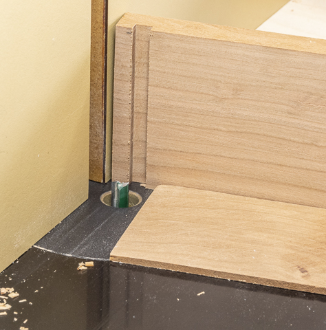
The box starts by ripping material close to the finished width on the table saw then to rough thickness on the bandsaw.  That’s followed by running it through the thickness sander to get the three different thicknesses needed.  Here the final two blanks are coming out of the sander.

After that the blanks are cut to final width on the table saw.  To cut them to final length a stop is set on the chop saw for repeatable results.


Here is the top piece of the film box.  As you can see the caliper reads out 35 millimeters.  It’s nice to have a caliper that can switch between millimeters, fractions or ten thousandths of an inch.  This also gives a closer shot of the stop setup on the chop saw.  There are three layers.  The bottom is a scrap that’s been cut so its right edge is flush with the blades cut.  Next is a thin layer that acts as a spacer so there is a free space that keeps sawdust from getting trapped against the length stop which is the larger oak piece.  Without the thin spacer sawdust could get trapped against its face and the cut piece would be too short.

This is the stack of pieces for the film box plus some extras in case I mess things up along the way.  Once the stop block is set on the chop saw it’s easy to cut another piece rather than taking the time to reset it up later.   If you look at the drawing you can see the channel that I will be cutting later.  It would be nice if it was centered top to bottom but that’s not the way it worked out.


Now at last I can start gluing pieces together.  The film box is glued up in two steps so I can take my time and get the pieces aligned perfectly.  This photo shows the first step where each half is glued up.  The cam clamps being used to hold them together are ones I just finished making.  If interested you can see how they were made under Cam Clamps.
             
After the two halves glue are cured they can be assembled into the final sub-assembly.

Next Up – Body Sub-assembly, Assembling the Film Boxes, Milling the Front & Back

Thursday, May 21, 2020

Wood Body Pinhole Camera - #5 Starting the Film Knobs

With the top, bottom and sides pretty much done I did a dry fit to make sure the method for winding and rewinding the film worked.  In doing so it occurred to me that adding a peg under the take-up spool would help keep it centered and aligned.  That way the spool is constrained between the pin and the recessed hole.  However, as the spool has a web across its bottom that has to be removed.  A little work with a sharp chisel, knife and round file took it out.  The top renderings show spool then to the right a view showing the webs and on the far right with the webs removed.  The bottom shows the bottom piece with the peg added on the right side.

The peg’s base is 3/8” in diameter to fit in a 3/8” hole that’s drilled 3/16” deep.  The upper part of the peg is cut down to 1/32” under 3/8” to fit in the spool’s end and just under 5/16” long.  It starts out as a ½” square piece and gets turned down.  In the photo below it's ready to have the last little bit removed and parted off.

Here is the finished peg partially inserted into the base.  Since it is a snug fit if I install it completely I probably won’t be able to get it out so will wait until the end to glue it in place.

The takeup/rewind knobs and their axles are next.  Each assembly has three parts; the axle, steel washer and knob.  The steel washer along with two rare earth magnets in the top firmly holds the assembly in place but allows for removal when changing the film.  Here is the drawing that shows how all those pieces go together.

The walnut knobs are first.  The already squared blank gets centers marked on both ends.  Here the driven end already has had the toothed drive set on the blank and struck with a wood mallet then reinstalled back in the lathe.  The blank is now ready to mounted between centers.

Once the blank is mounted taking it from square to round can begin.  I use the roughing gouge shown to do that being careful to get a consistent diameter the entire length.  The tolerance in diameter is plus or minus .008”.

After the cylinder is turned the blank is taken off the lathe, the drive center removed, a four-jaw chuck is installed and the blank reinstalled in it.  I use the live center in the tail stock to assist in making sure the long axis of the blank is in line with the lathe axis when tightening the chuck.  The next step is to face off the end of the blank to make sure the end is square with the center line of the blank.  That’s followed by chucking up a 1” Forstner bit to make the recess for the steel washer.  Here is what that looks like.

Next is to drill the 5/16” hole where the axle will get glued in place.  When that’s done the drill and drill chuck are removed from the tail stock.

A live center is installed in the tailstock, brought up snug against the outer edges of the axle hole and the outside face of the knob is turned down to its final diameter.

Last is to part off the knob.  Here in the top photo you can see where the roughed-out knob is ready to be cut off the blank.  The small cone shaped piece will stay with the knob and is there for a good reason which will be covered later.  The bottom photo shows both roughed-out knobs.

Turning the axle for the knobs is next.  It starts with a rectangular piece turned down to just 1/64” oversize as shown in the top photo.  The blank is flipped end for end and the same turning is done on the opposite end.  The bottom photo shows both ends turned.

The question naturally is why not finish turning the first axle to size before starting on the second?  If you look at the photo below you can see a different center installed in the live center.  The original one has an adjustable point and a larger outer ring holding the piece in place.  The photo below has only a fixed conical point.  With the original point and ring center I could not turn the axle small enough without hitting the live center.  I wanted to use it rather than the conical point to reduce the chance of splitting the blank while doing the rough turning.  With the blank turned very close to its final diameter I felt comfortable using the conical point to finish fitting the axle to the knob.

Here you can see the end result where the axle is friction fit to the hole in the knob. 

Now all that needs to be done is to lightly mark the insertion depth and the overall length as shown below then part it free.

Once cut free the full length of the axle is 5/16” in diameter which friction fits into the knob just fine.  However, part of the axle goes through the hole in the top of the camera and rotates when winding and rewinding the film.  This hole is also 5/16” so the axle needs to be a little smaller than that.  If I had 21/64” bit I could just drill a larger hole but I don’t so the next best thing is to mount the axle in a small chuck and sand enough off its diameter to rotate freely.

Cutting the slot in the axle where it will engage with the web in the film spool is next.  That’s done on the bandsaw.  A hole is drilled in a block the same size as the axle then a rip fence is set so the blade hits the axle dead center.  Last a crosscut fence has the block clamped to it and the cut can be made.

There is only one more step to complete that axle.  Since the web in the film spool is wider than the bandsaw blade kerf it needs to be widened a bit.  The left photo shows the axle and little file that will be used.  The right photo shows how the axle will set in the film spool albeit upside down from how it will be installed.
Next Up – Completing Film Knobs & Starting the Film Boxes


Thursday, May 14, 2020

Wood Body Pinhole Camera - #4 Routing Dados, Tenons, Machining Top & Bottom

Here is the router table setup to cut the ¼” wide and ¼” deep dados.  The cut depth and location has already been set using some of the test material.  Some things to notice about the setup.  First, to keep the blank square and to minimize blowout when the bit exits the piece there is a ½” thick backer board.  It also has a handle to help me control the cut.  Next, the blank has not been cut to size.  It is too wide and the side piece is still attached.  Width is oversize because I anticipate a little blow out on the back side even with a backer.  If so, it will get cut away when I trim the blank to its final width.  The extra length is so if the first cut goes bad it can be cut off and redone.  Last is the thin plywood spacer under the piece shown better in the bottom photo.  I will go into what that is for next.

In this closeup the piece has been run through the router.  The width and location are set and correct but the depth of the cut is way short due to the spacer holding the piece up.  That’s done because trying to remove all the material in a single pass can lead to problems like overloading the bit and breaking it or since it’s a closed cut the waste can pack in the cut leading to overheating the bit and ruining its cutting edge.

Here is the second pass made using a thinner spacer which makes the cut deeper.

This is the third pass which cuts the dado to its full depth.  Another way to make the cut would be to raise the bit in three steps.  I didn’t do that for a couple of reasons.  First, using spacers for the first two passes leaves an opening under the blank allowing the chips an easy way to escape preventing it from packing them in the cut.  For the third pass there is a lot of free space within the dado and not a lot is being removed during this final pass.  The other reason is once the bit and fence are set with spacers I can cut as many pieces as I want and they will all be the same.  If the bit were changed for each pass and during the last pass on the last piece a problem developed where I needed to make another piece the bit would have to be reset to start from the beginning.  Trying to get the exact same depth of cut can be done but it sure is fussy time-consuming work.

Routing the tenon to go into the dados just completed is next.  The same three step routing process and bit are used although the distance the bit is from the fence is changed. 

Once the tenons are cut the fit into the dados is checked.  Because the dado is cut using the full diameter of the bit they are all the same width.   However, the thickness of the tenon will vary ever so slightly because the cut removes a fixed amount of material rather than cutting the tenon a fixed thickness.  If everything were perfect the tenons would be the same thickness and would fit with no problem.  Unfortunately, I don’t live in a perfect world and there is some variance in the thickness of the pieces.  It’s not much maybe a few thousandths of an inch from one side to another but that’s enough to impact the fit.  The fix it to mark where the tenon needs to be trimmed and clean it up.  To do that the thick part of the tenon gets marked then clamped down.  The top photo shows my clamp assembly.  The bottom photo shows the pencil mark where material needs to be removed and next to it is the file I will use.  Filing just enough to remove the pencil line generally takes care of it.

Ripping the top, bottom and sides to their final width is next.  Most of the time I keep a combination blade on the table saw.  It’s a comprise design that does a pretty good job for both ripping and crosscutting.  Still, using a blade specifically designed for ripping does give a better cut so I changed out the combination blade for a rip blade to make the cuts.  Below on the left is the combination blade and on the right the rip blade.  Note the difference in tooth configuration.

In order to clean up any chipping from the routing I start by taking a very thin cut from one side then cutting it to the finish width on the other.  This is what the dry fitted box looks like.  Nice clean tight joints where everything lines up.

Drilling holes in the top for the knobs and magnets is next.  The top photo shows the plan and the bottom one shows the layout with the centers punched to make centering the drill easy.

The drill press makes quick work drilling through holes for the knobs and their axels.  The holes for the magnets are drilled just deep enough so they will be flush when installed.

Installing the threaded insert in the bottom so the camera can be mounted on a tripod is next.  The insert has wood screw threads on the outside and machine screw threads on the inside.  I have a couple different types of inserts.  The one below on the left is plated steel but is longer than the bottom is thick and would stick out.  The middle one is also a little long but it is made from brass and unlike the plated steel one I can shorten it to fit without worrying about it rusting.  Besides I like the look of brass with cherry.  The one on the right is the shortened one that will be installed.

A 10 mm bit is used to drill a hole for installation.  It is just a little larger (.0187”) than the 3/8” bit used for maximum strength which is not needed here and makes for a much easier installation.  Here in the top photo you can see where the insert has been screwed onto a partially threaded rod along with a spacer and wing nut all chucked up in the drill press.   To install I lower the chuck using the drill’s handle and turn the chuck by hand.  As I have said before don’t turn the drill press on to install the insert or things will get really exciting in hurry and not in a good way.  Using the drill press to install the insert most of the way makes sure it is plumb and square.  The bottom photo shows the underside of the bottom with the insert installed.


Next Up – Starting the Film Knobs

Thursday, May 7, 2020

Wood Body Pinhole Camera - #3 Ripping to Thickness & Changing Bandsaw Blade

Ripping the boards down to the various thickness required are next.  That’s done on the bandsaw.  Here is the setup ready to go.

These are part of the rough-cut pieces ready to be run through the thickness sander.  As you can see there are some burned areas left by the bandsaw blade.  In looking at the sawdust it also shows signs of being a little burned.  This has been going on for a little while so I think it’s time to retire this blade and put on a new one. 

Ever wonder how to change a bandsaw blade?  Well, here is the way I go about it.  By the time I am done you will see why I use the ½” blade almost all the time and don’t change to a different size frequently.

The photo on the left is how I keep the bandsaw ready to go.  The photo on the right has the light and magnetic fences stored on the bandsaw taken off and the doors open.  If you are wondering what the parts are in the bottom right, they are the old blade guides the saw originally came with.

Next is to remove tension from the blade.  I typically do this after I get done with the saw for the day but because it had just been in use the blade was tensioned.  The white round zero clearance throat plate has also been taken out.  The guides near the top of the photo have been loosened and pulled back from the blade along with a second set under the table.   On the right circled in red is a tapered bolt-pin that still needs to be removed.  Its purpose it to keep the cast iron table flat on both sides of the slot.  The slot is where the blade will come out. 

Cleaning the tool is next.  I blow or vacuum all the dust off inside and out.  The old blade is removed, set aside then the wheels are cleaned and the bearings checked along with the other moving parts. 


A bandsaw blade comes coiled up similar to this only in a tighter coil.  Unwinding the blade can be fun.  Nothing like playing with a 133” long piece of coiled spring steel with 399 razor sharp points just ready to rip you to shreds.  Blades less than ½” wide are not too bad to work with.  This blade at ½” wide is OK as long as your careful but I have a 1” wide blade that is another story.  When it’s time to uncoil it, I have been known to go outside in the yard, throw it up in the air then run away while it uncoils and tries to eat me.

Once uncoiled the blade in installed in the saw, tension slowly added, the tracking checked and the adjustment of the guides can begin.  Here is what the adjusted guides look like.

The first step is to set the guides on either side of the blade just behind the gullet of the teeth.  With that done the top guide that’s behind the blade is set so there is just a tiny gap between it and the blade.  The top photo shows that done.  Next is setting the tiny gap between the side wheels and the blade.  You can use a sheet or two of paper but I just eyeball it.  When adjusted correctly and the saw running the wheels do not spin until pressure is applied to the blade and cutting begins.

As mentioned earlier there is a second set of guides under the table that need to be adjusted just like the set I just did only with a lot less room to work and it’s hard to see what you are doing. 

Two things remain before I can call it done.  A test cut is made, here a scrap of quarter sawn white oak is used and the results speak for themselves.  A nice even smooth burn free cut even at the bottom where the cut was made through a knot.  The last thing is to coil up the old blade and set it aside for a backup in case this one breaks or I need to cut some wood of questionable origin that might have a surprise rock or nail buried inside. 

Once all the pieces have been run through the thickness sander, I go through deciding which piece to use for what and laying the blanks out working around any flaws.  Speaking of flaws this is the piece of walnut that will be used to make the knobs.  The problem areas that I need to stay away from are circled in white.  The clean part at the top above the horizontal line is what I will cut off and use.

This is the final layout with each piece marked and labeled.  There are some just noted as "test".  They are for just that, testing machine setups and joint fitting.  They are also big enough that I can make a replacement if an irreversible problem comes up or something goes wrong and I have to start over on a part.

Cutting the dado joints in the top and bottom are first.  Here is how the top, bottom and sides will go together.

There are a couple of ways I cut dados.  Using a table saw with a stacked dado blade is one way or using a router is the other.  For these a router will be used.  That’s because since the joints will be exposed, I want an absolutely flat bottom and square corners.  My dado blade cuts a pretty flat bottom but because of the way some of the teeth are ground their points leave a tiny little angled cut line where the side meets the bottom.  You can see the different teeth in the left photo.  A router on the other hand cuts a flat bottom with a sharp square corner.  The photo on the right has the left dado cut with a router and the one on the right is cut with the table saw showing the tiny little angled cut line.  Both are ¼” wide and deep.


Next Up – Routing Dados, Tenons, Machining Top & Bottom