

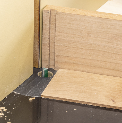
In this closeup the piece has been run through the
router. The width and location are set
and correct but the depth of the cut is way short due to the spacer holding the
piece up. That’s done because trying to
remove all the material in a single pass can lead to problems like overloading
the bit and breaking it or since it’s a closed cut the waste can pack in the
cut leading to overheating the bit and ruining its cutting edge.

Here is the second pass made using a thinner spacer which
makes the cut deeper.
This is the third pass which cuts the dado to its full
depth. Another way to make the cut would
be to raise the bit in three steps. I
didn’t do that for a couple of reasons.
First, using spacers for the first two passes leaves an opening under
the blank allowing the chips an easy way to escape preventing it from packing
them in the cut. For the third pass
there is a lot of free space within the dado and not a lot is being removed
during this final pass. The other reason
is once the bit and fence are set with spacers I can cut as many pieces as I
want and they will all be the same. If
the bit were changed for each pass and during the last pass on the last piece a
problem developed where I needed to make another piece the bit would have to be
reset to start from the beginning.
Trying to get the exact same depth of cut can be done but it sure is
fussy time-consuming work.

Routing the tenon to go into the dados just completed is
next. The same three step routing
process and bit are used although the distance the bit is from the fence is
changed.

Once the tenons are cut the fit into the dados is
checked. Because the dado is cut using
the full diameter of the bit they are all the same width. However, the thickness of the tenon will
vary ever so slightly because the cut removes a fixed amount of material rather
than cutting the tenon a fixed thickness.
If everything were perfect the tenons would be the same thickness and
would fit with no problem.
Unfortunately, I don’t live in a perfect world and there is some
variance in the thickness of the pieces.
It’s not much maybe a few thousandths of an inch from one side to
another but that’s enough to impact the fit.
The fix it to mark where the tenon needs to be trimmed and clean it
up. To do that the thick part of the
tenon gets marked then clamped down. The
top photo shows my clamp assembly. The
bottom photo shows the pencil mark where material needs to be removed and next
to it is the file I will use. Filing
just enough to remove the pencil line generally takes care of it.

Ripping the top, bottom and sides to their final width is
next. Most of the time I keep a
combination blade on the table saw. It’s
a comprise design that does a pretty good job for both ripping and
crosscutting. Still, using a blade
specifically designed for ripping does give a better cut so I changed out the
combination blade for a rip blade to make the cuts. Below on the left is the combination blade
and on the right the rip blade. Note the
difference in tooth configuration.

In order to clean up any chipping from the routing I
start by taking a very thin cut from one side then cutting it to the finish
width on the other. This is what the dry
fitted box looks like. Nice clean tight
joints where everything lines up.

Drilling holes in the top for the knobs and magnets is
next. The top photo shows the plan and
the bottom one shows the layout with the centers punched to make centering the
drill easy.

The drill press makes quick work drilling through holes
for the knobs and their axels. The holes
for the magnets are drilled just deep enough so they will be flush when
installed.

Installing the threaded insert in the bottom so the
camera can be mounted on a tripod is next.
The insert has wood screw threads on the outside and machine screw
threads on the inside. I have a couple
different types of inserts. The one
below on the left is plated steel but is longer than the bottom is thick and
would stick out. The middle one is also
a little long but it is made from brass and unlike the plated steel one I can
shorten it to fit without worrying about it rusting. Besides I like the look of brass with cherry. The one on the right is the shortened one
that will be installed.

A 10 mm bit is used to drill a hole for
installation. It is just a little larger
(.0187”) than the 3/8” bit used for maximum strength which is not needed here
and makes for a much easier installation.
Here in the top photo you can see where the insert has been screwed onto
a partially threaded rod along with a spacer and wing nut all chucked up in the
drill press. To install I lower the
chuck using the drill’s handle and turn the chuck by hand. As I have said before don’t turn the drill
press on to install the insert or things will get really exciting in hurry and
not in a good way. Using the drill press
to install the insert most of the way makes sure it is plumb and square. The bottom photo shows the underside of the
bottom with the insert installed.

Next Up – Starting the Film Knobs
No comments:
Post a Comment