Router Plane

Monday, December 26, 2016

Dining/Game Table - #18 Flattening & Sizing the Leaves, Making the Pegs

I could now start running the pieces through the thickness sander to clean up any slight misalignments of the joints and flatten.  I can’t use the planer because it can only do 12 ½” wide pieces and the panel is 16”.

Because I am pushing the maximum size of the sander it creates some problems.  First, it is rated for a 16” sanding pass, but that’s nominal.  Effective width is around 15 ½” so it leaves a little ridge on each side that has to be frequently removed.
Ridge to be Removed from Thickness Sander
Second, because I am at the width limit I can’t shift the piece from side to side which means the glue joints hit the same exact place on every pass and builds up on the sandpaper as in the photo below. 
Glue Build-up on Sanding Abrasive

If very much builds up it causes a nice burn mark the full length of the piece along the glue joint.  The fix is to frequently stop and scrape the glue residue off the sandpaper.  Unfortunately, that is a fix with a decreasing return.  Each time I do clean it up the time before I need to do it again is less.
Temporary Cleanup of Glue

Third, because of the piece width I can remove only about 1/32” per pass which does not sound like much but in one pass that means it is converting over 26 cubic inches of red oak into sawdust.

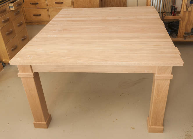
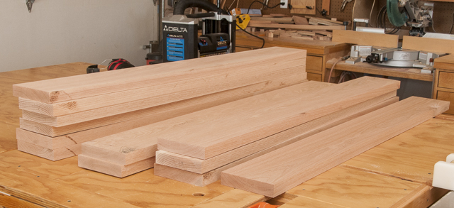
All in all, it took me the better part of two days to take the 44 square feet of surface area on both sides clean up slight misalignments of the joints and flatten, then rip to final width.   There is still a lot of work to do but this is what it looks like.

Flattened Table Leaves Cut to Width but Not Length

My next step is to cut the four top sections to length.  First choice for cutting a long heavy piece to length would be my chop saw but that won’t work because it cannot cut a piece this wide.  I do have a crosscut sled that makes cutting large pieces work pretty well on the table saw.
Crosscut Sled on Table Saw

I started by squaring up one edge then making a second skim cut.
First Edge to be Square Cut

The cut on the other end to finish length is done in a two-step process.  First is to make a cut about a 32nd of an inch long using a stop block set up on the sled. 
Cutting Leaf Slightly Long

The second cut is to finished length.  I don’t want to move the stop block so use a spacer 1/32” thick to make that last skim cut.  This way all the pieces will be cut the same length.
Stop Block with Shim Ready to Make 2nd Skim Cut to Final Length

I thought about the next steps and decided rather than continue on with finish sanding, routing the edges of the top then end up installing the pegs that will align the leaves I would start with the pegs.  Once they are all in place I will move on to finish sanding and routing the top edges.  I plan on taking this route in case there is some slight misalignment when laying out and installing the pegs that requires some work on the leaves.  No sense in doing the finish work twice.

Before I actually started drilling holes in the leaves for the alignment pegs I did some testing.  I sure don’t want to make any irreparable mistakes on one of them.  That would mess up more than my whole day.  Starting with some scraps from the leaves I laid out three peg locations then using a self-centering doweling jig drilled 1” deep by 3/8” diameter holes in both pieces.

Next came the pegs.  I had some 3/8” fluted dowels that I thought might work out.  Some five tries later I had developed a shape I was happy with.  I was not happy in how they looked or the material hardness so decided to try a different wood.  Since the table is out of red oak and I have a lot of scraps to work with I tried that.  It worked out better but oak is an opened grained wood and after turning it on the lathe I decided I wanted a close grain wood.  Both maple and cherry came to mind but because the maple is soft maple I opted to go with cherry.

Peg Tests

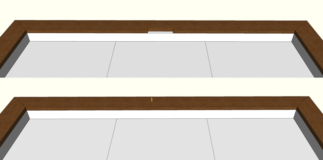
Last test is using the final peg design install them in the leaf scraps and check to see how they come together.   Here is a pair of photos, the top one has the pegs installed in one piece.  The other has the holes that will go on the pegs.  The bottom photo shows what the two leaves when almost pushed together.  Sizing the tapered end of the pegs is like Goldilocks and the three bears.  You want the pegs to fit just right.  Too loose and the leaf will be free to move around and not be aligned.  Too tight and while it will align it will take a gorilla to put leaf in place or remove it.  It’s a balance that is measured in a few thousand’s of an inch.  Throw in the humidity change between New Mexico and Arkansas and it becomes even more interesting.  Actually I am going to leave them unfinished and removable so if needed they can be easily modified.

Testing the Pegs and Alignment Process

With the testing done I started on making the 18 pegs needed.  They start with a cherry blank 7/16” square.  That gets inserted through the 4-jaw chuck on the lathe.  The green tape on the tool rest has my reference measurements laid out on it.  Since so many pegs need to be made this will help speed things up by not having to measure each one.
Square Peg Blank Ready to Turn

The square blank is turned round and to a rough size.  Here I am using a 3/8” wrench to check the size of the turning.  It works really well; I don’t even have to turn the lathe off to check the size.  When it just slips over like this I quit turning.  The wrench may say 3/8” but it is .007” over. 
Using Wrench to Check Peg Diameter

I transfer the measurements from the green tape by eye then turn the tapered end.
Peg Ready to be Parted Off

The rough peg is cut off and driven through a die exactly 3/8” in diameter.  This is where the 3/8” wrench being slightly oversize is a good thing.  As much as I try it’s really hard to hit an exact size so being a smidge over gives me a little leeway. 
Die for Sizing Peg

The peg is then put back in the lathe for sanding which removes just enough material for a snug fit into the drilled 3/8” holes.  Three pegs down and 15 to go plus a couple extras.  Turning the cone shaped end of the pegs for a final fit will come after I drill the holes in the leaves and do finishing alignment.


Next Up – Drilling Peg Holes & Routing Top Edges

Monday, December 19, 2016

Dining/Game Table - #17 The Top, Biscuits, Glue-up & a Change

I started on the top by ripping the number 2 board of the first half to it’s final width plus a sixteenth inch then clamped the first board to it to make sure the glue joint will be tight and the boards will lay flat.  With a tight and flat joint I made the final trim of the number 2 board to width.

Board #1 & #2 Clamped Together

With that done I use the sliding miter saw to cut a clean square edge at each end of all the pieces.

To help keep the glue joint faces flush with each other I will use biscuits.  These are not baking powder biscuits that are good with gravy but rather oval pieces of compressed wood that fit in matching slots.  The cut is made with a biscuit joiner which uses a small circular saw blade to cut a crescent-shaped hole in the opposite edges of two pieces of wood. 
Biscuit Cutter & Biscuit

The biscuit joiner is set to center the cut in ¾” material.  My top is going to end up between 1” and 1 1/8” thick and I want the biscuit pretty much in the center.  The tool has a secondary adjustable fence to set this height but it works by registering the cut from the top instead of the bottom.  In testing I found this fence had some play in it.  It could cut slots not perfectly 90 degrees to the glue joint, at slightly different heights or both.  What this means is when I go to glue everything up the misalignment could cause me problems.   My solution is to not use the secondary fence but to simply add a 1/8” thick spacer made out of Masonite under tool thus raising the center of the cut so it is centered on a 1” thick top.

Biscuit Cutter with Blade Exposed & Resulting Cut

To make the actual cuts I clamped the board down tight to the workbench.  This is critical since the biscuit cutter references off the bottom so if the bottom of the board and the bottom of the biscuit cutter is not tight to the workbench any gap will result in that much of an offset when you go to join the two boards.
Biscuit Cuts in Test Piece

In the photos below the pieces I am joining are left over tests from when I was surfacing the top pieces down.  In the top photo you can see the two biscuits set partially down in the cut and in the bottom one where I drove the pieces together.  The biscuits held the two pieces in alignment giving me a precise smooth joint between them.
Biscuit Test Fit
Next using a scrap piece of oak as a story stick I laid out the locations where I wanted to install the biscuits.  Now all I have to do is align its end with the edge of the top and mark the locations.  Since there will be 10 sets of joints this will speed up the layout plus making it more consistent.

Story Stick for Marking Biscuit Locations

With the biscuits laid out I can clamp the first top piece in place and start cutting it’s biscuit slots then move on to the second piece. 

Production Biscuit Cutting

When both pieces have the biscuit slots cut I can do a test fit.  Here is the part of the first piece set in the clamps with the biscuits in place.  Next is to add the second piece, tighten down the clamps, check where the two pieces come together for gaps and make sure the faces are flush.  Last, I lay a straight edge across the joint to check to see if both pieces are flat and in the same plane.  If everything checks out I am ready to unclamp the pieces, remove the biscuits and glue the two boards together.
Biscuit Test Fit
As is normal it seems like a race against time when doing a glue-up.  In this case I need to put glue in the biscuit slots, then on the first piece edge and last on the upper half of the biscuits where they will go into the second piece.  One thing that adds to the tension is that when the biscuits come in contact with the glue they start to expand. On one hand this is good as they lock both pieces together.  On the other if you are too slow they can expand so much it’s tough to force them into the slot and get the two pieces of the top pulled tightly together so you end up with a gap free joint.   When it goes well and the clamps are tightened you get a flush joint, a flat surface and no indication of the biscuits.
First Two Board Glue-up

After letting the glue cure overnight, I take off the clamps and check the results.  Everything is within tolerances so I can now go through the process to add the third board.
  • Test clamp to make sure glue line will have no gaps and correct as needed.
  • Rip to width plus a sixteenth inch
  • Cut ends square
  • Layout biscuit locations and cut
  • Test clamp with biscuits checking face alignment and flatness
  • Glue-up

Completed 3 Board Glue-up

After letting the glue cure overnight, I took off the clamps and checked the results.  Everything was good so I could set it aside and go through the whole process three more times.  The plan was to glue-up two of the 3-board sections to create one of the two pieces that will make up the top.  As with other parts of this project the plans changed.  When I got done with the 3-board glue-up it felt heavy.  That was confirmed when I put it on the scale and it showed 25 pounds.  Gluing two of them together as I had planned would have yielded a 50-pound leaf.  Imagine taking a 32” x 52” table leaf that weighs 50 pounds on and off, maybe not the best plan.  Four 16” X 52” leaves at 25 pounds each sounds better.  When I increased the top thickness 50% from ¾” to 1 1/8” I also increased the weight by 50%. DUH! 

All 4 Leaves Set In-palce

With all four sections glued up I sat them on the table to get an idea of what it will look like.  I think the extra thickness is good visually.


Next Up – Flattening & Sizing the Leaves, Making the Pegs

Monday, December 12, 2016

Dining/Game Table - #16a Christmas Ornaments

It is now early December and at my wife’s suggestion I find that I need to make some Christmas ornaments for gifts soon.  As a result, the Dining/Game table work is on hiatus for a week or so.  

The ornaments are going to be turned on the lathe and are not huge.  For material, I went through my scraps and came up with three pieces.  First is a split cutoff from one of the rough sawn oak planks I am using to make the table top.  Second is a cherry remnant from the Maloof Rocking Chair that had a crack in the center and last is a cutoff from a cherry/cocobolo laminated piece I had glued up for the neck of an acoustic guitar I made some years back. 
 
The cracked cherry was easiest as I just cut square blanks working from the outside in discarding most of the cracked area.  The cherry/cocobolo laminated piece was the next easiest.  I worked from the existing two flat square faces in until I got a square blank with the cocobolo centered.  The oak took a little longer, first I flattened the rough sawn faces but at 1 3/8” thick it was a little thin so I laminated two pieces together.   When done, I had enough blanks for probably three times the number of ornaments I am going to make.  That’s not a problem I will just put them away until I need them for something else later.

The process for doing these turnings are a bit different than most of the things I do.  There is no real detailed plan, I will at best have a rough sketch to work from or just an idea.  That’s the case of the pieces in the photo below, no drawn-up plan at all, not even a sketch.  I used the long oak blank for a pair of Christmas trees one convex and one concave tuning them until they looked right.  What’s shown is just before I cut them apart.  The dark lines are made by making a small groove then friction burning it by holding a wire in the groove with the lathe turning.

After the Christmas trees, I made a few ornaments out of the solid cherry blanks then finished up with two out of half of the cherry/cocobolo laminated blank.  I did end up making a template for the oval shaped piece on the left.  I wanted a constant symmetrical curve and thought it would help. 

For the hangers I took a regular wire ornament hanger, straightened it, cut it in half, bent it around a drill and used a pair of pliers to twist the ends together.  Using cyanoacrylate (super) glue I glued them in a 1/16” hole I had drilled in the ornaments while they were still on the lathe.

Some of the pieces ended up pretty close to the sketch and some, well, not really close at all.  When finished, I had 8 ornaments of various designs.  Here they are along with my air-brush setup ready to finish.


Using the air-brush I sprayed a couple coats of lacquer on the ornaments let them set overnight and finally lightly wet sanded them with a 4,800 grit pad. 


All done and just in time too.  Now it’s back to working on the table top.


Next Up –  The Top, Biscuits, Glue-up & a Change

Saturday, December 3, 2016

Dining/Game Table - #16 Routing the Top Rail & Starting on the Top

Now that I had the arm rail attached to the table I could work on the last two parts of it’s router work.  I held off routing the top outside edge because I want the round over to flow seamlessly around the corner.  If there had been any mismatch at the miter joints then I would have needed to fix that before routing or would have had to re-route the edge.  I also wanted to use the hard corner where the two pieces came together for alignment.  Because of the change in grain direction at the corners I back each end cut up to reduce the chance of the bit blowing the corner out.  Another one of those experience lessons.
Backing on Corner for Routing

For the round over I will use a ¼” radius bit.  I went with a slightly larger radius here than on other parts of the table because this edge is where people will be leaning while playing games.  I think the larger radius will just make it a little more comfortable. 
Routed Edge


This is a little closer look.  Here on the left you can see how the backed-up corner prevented any blow out as the router exited the cut.  The non-routed edge is the chipped one seen before.  The photo on the right is after I had routed that edge.  You can see the chip got completely cut away when routing that edge. 
Left, First Cut & Right Finished Corner


With the nice soft rounded edges done so far it makes little sense to leave a hard 90-degree point at the corners.  To take care of that pointy hip-killing corner the last bit of routing will be to round it over using a 3/16” radius bit.  This is a little tricky in that you have to hold the router horizontal and there is very little for the router base or the guide bearing to ride on.  All which make it easy to get out plumb/level causing a misaligned cut.
Routing Corner

A couple of gentle passes with the router gets rid of the hard edge, softening it up quite a bit and giving me a 95% completed corner.  I ended up with a little burning from the router bit and the round over needing a little hand work to make it smoothly flow in all three dimensions.  Both are easily take care of with a little hand sanding.
Left, Routed Corner & Right, Finished Corner


This completes the work on the arm rail except for one thing, how to lock the table top in place.  We have narrowed it down to two options first is a notch in the rail and second is to use a removable brass locating pin.  Until that is decided I will do some work on the removable table top.
Top, Notch & Bottom, Pin


A couple of weeks ago I had milled the rough sawn oak planks into oversized straight, flat and square boards to be used for the top.  It was my hope that they would stay straight, flat and square the way I had left them.  Well, the red oak gods must be smiling at me, after checking all 12 pieces I found that everything was as I had left them.   When I originally was surfacing the planks I just took each one down to where the surface was 99% good but not necessarily to a consistent thickness.  Now I did two things, sorted the pieces by thickness and selected the face needing the most work. 
Top Planks Sorted by Thickness

With that done I started with the thickest piece and ran it though surface planer cleaning up the worse looking face until it matched the next thickest piece.  Planing the worse face both pieces were then run through the planer until they matched the third thickest then that one was added to the batch.  I kept this process up until all the pieces were the same thickness.   Here I stopped and reviewed the faces again deciding which needed work and which were done keeping in mind that I need one perfect face and one almost perfect face.  I kept this process of making a pass through the planer and evaluating the faces until I got what I needed.  The thickness at this point is 1 3/16”.

Planing Setup

With all the boards the same thickness and all but the tiniest blemishes removed (the final surface work will remove them) I took each of the 12 boards through a 3-step process.  First, pick the best-looking face for the exposed table top then select the best-looking edge.  Second, put the piece in the routing jig with the best face up and the best edge out.  I will run the router along this edge to get a dead straight surface for gluing.  Third, cut the piece using my rip blade on the table saw to get an edge parallel to the routed edge about 3/16” oversize.  Here is a shot of all phases in process.

Once that was done I spent about 30 minutes shuffling all the pieces around until I was satisfied I had the best arrangement I could get where the grain and color flowed from one piece to the next. 
Top Pieces Ordered for Grain & Color Flow

The completed top consists of two removable pieces each made up from six boards.  My general plan for assembly is to glue two boards together then add the third and finally run them through the thickness sander.  This will flatten them and take care of any miss-match at the glue joints.  I will then repeat to get two flattened sub-assemblies then glue them together to form one completed half of the top.  My hope is for the last glue-up to result in a perfect joint but in reality, I expect some minor differences.  At least that’s the plan, we’ll see how it actually plays out. 


Next Up – Christmas Ornaments

Monday, November 28, 2016

Dining/Game Table - #15 Assembling & Installing the Arm Rail

While I wait to see if the pieces for the table top are stable I will go back and work on the arm rails.

Because the table will be disassembled for delivery I wanted to make sure the four arm rail pieces go back together just the way they are now.  To that end I decided to use pocket hole screws to lock the pieces together.  However, before I do that I need to route the inside and bottom edges for two reasons.  First, I will not have to blend the inside face routed edges by hand.  I had enough of that when doing the legs.  Second if I waited until the arm rail was installed the outside bottom edge would be really awkward to get to.  Here is my prototype, note the different radiuses of the round overs.
Arm Rail Test

Process for routing is to clamp a piece face down then route the inside bottom round over with a 1/8” radius bit then the bottom outside edge with a 3/16” radius bit.  With the bottom done I flip the piece over and route a 3/16” radius round over on the top inside edge.  This leaves just one edge and the corners to do after the rail is installed.  More on that when I get there.
3 of 4 Round Over's Done

After completing the routing I can start working on drilling the three pocket holes at each miter joint.  Going back to my prototype I slightly changed the location of a couple of the holes for more equal spacing or to move the pocket hole a little farther from the edge then transferred the locations to each piece.
Marking Pocket Hole Locations

With the locations marked I can start drilling.  Only problem is the holes are at a right angle to the 45 degree miter joint which means that when I put the rail in the jig it is at a 45 degree angle and the jig’s clamp will not hold the rail in place.  To fix I clamped a few scraps together to make a brace that holds the arm in the right place.  The catch is I have to adjust the brace for each screw location.  Not hard, just little time consuming.
Jig Set-up for Drilling Pocket Holes

After I drilled the first hole I decided to add a stop to help in uniformity.
Stop Added to Set Up

Once all the screw holes done I can start assembling the pieces.  I have found the only real problem in using pocket screws is keeping the pieces aligned when screwing them together.  Because the screws go in at an angle if both pieces are not securely clamped in place or if there is a gap between them you can end up with a slight misalignment.  Usually it’s a slight upward shift of the second piece.  Now I am after a dead flush miter joint here and a shift would cause me some real grief.  Kreg has a flat plate vice-grip style clamp that does pretty good but in this case I want to make darn sure nothing moves. 

Kreg Clamp

It’s time to go a lot heavier duty and use some old fashion malleable iron C-clamps.  With them I can apply enough torque that the oak will cry for mercy and won’t dare move.  Since I am really going to apply a lot of pressure and don’t want the wood dented from rough spots on the clamping faces so I checked them for smoothness and found a couple of bad spots.  A little work with a file and they were nice and smooth.

Smoothed C Clamp Faces

Now I could set the arm rails up on blocks put on the clamps and run the screws in.  With the first joint done I worked my way around clamping and installing screws.  When I got to the last joint I was pleasantly surprised in that it was less than 1/16” off of perfect alignment.  That certainly exceeded my expectations. 
Installing Screws

With all the joints securely screwed together I flipped the assembly over and moved it into place on the table.  Here is how it looks, I think it defines the perimeter of the table and ties it all together but then I am biased.
Arm Rail Set In-Place

Taking a closer look, I am quite happy on how tight and flush all the joints are.  This is typical of the fit.  If you look close at the bottom horizontal piece right at the joint you can see it is chipped.  That chip has been there all along and is not a problem because when I route a round over of that edge it will disappear.
Perimeter Edge to be Routed

Next is to attach the arm rail assembly to the table.  This is done by installing a screw up through the spacer into the arm rail. 


There are quite a few screws already in the spacer.  To make sure I did not have a conflict I needed to make sure I knew where those screws were.  Some I could see and on some I had what I thought were layout lines but was not for sure.  To verify I took a rare-earth magnet set it on the spacer close to the layout line.  Sure enough the magnet was strong enough to pull itself over and be centered on the screw which just matched up with the layout lines.  Based on that I located where my pilot holes go.  They are marked in green to help me keep things straight.  All I needed to do now is to drill 24 holes.
Locating Screws with Rare Earth Magnet

With the pilot holes done I centered the arm rest assembly on the table and clamped it there.  With the clamps holding it in place I got on my back crawled under the table and drove the screws in.  I should mention that the spacer is almost 13/16” thick and the arm rail is slightly over ¾” thick which together totals almost 1 9/16”.  The screws are 1 ½” long the difference being a shade under 1/16”.  I probably would have been alright to just drive them in but that’s cutting it a little close so I added a 1/32” thick washer for peace of mind.  Here is the view from under the table looking up at the screw going through the spacer.

Screws Holding Arm Rail In-Place


Next Up – Routing the Top Rail & Starting on the Top