Router Plane

Monday, April 25, 2022

Porch Swing/Glider - #7 Installing the Arms, Testing Seat Height & Disassembly

With both the arm and its support done they could be assembled and attached to the swing.  That starts with a pair of countersunk pilot holes drilled into the top of the arm for the screws that get run into the support.  These holes are used to mark the pilot hole’s location on the support.  To assure the holes are square I use the drill press.  Clamping the support to the fence keeps one face square to it while the square aligns the other face with the table.

Once they are drilled it’s a simple matter of lining the 2” screws up with the just drilled holes in the support and running them in.

Next is to screw the back end of the arm to the back brace.  Since it’s not practical to put the swing in the drill press to keep the hole square while being drilled a simple guide is used.  It’s just a scrap with a hole drilled in it the same diameter as the finished hole made using the drill press so it’s square.  In use the block (it has FOREST on its end) is held tight against the back support which holds the drill in the proper position while the hole is being drilled.  The same process is used to add the screws attaching the arm support to the seat brace.

The last pieces, for now, that go on the swing are the long supports that get screwed to the seat/back braces.  Below they are shown in blue.

My plans for attaching the long supports were to install a screw from the bottom into the seat/back brace per the X-Ray drawing on the left.  However, when the time came it became evident that wasn’t going to work as I would have had the screw holding the arm support on and the screw holding the long support trying to occupy the same space shown circled in red.  The solution is shown in the right photo.  Bringing in the second screw in at a 15-degree angle from the back pivots it so it does not hit the first one.

Below are a couple of tests I did holding the screw at the same angle in both but changing the point at which the screw exits the top of the long support.  The left photo was the first try and it looked a little close so I moved the exit point a little to the right which gives more room between the screws.  The problem is that because the screw goes in at an angle, I was worried that the right example could cause the long support to twist a little bit counter clockwise where the one on the left is more centered and probably wouldn’t have that problem.   Based on that concern the left example will be used.

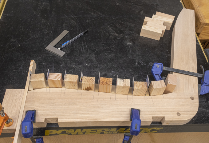
Here is the setup used to drill the angled holes for the screws.  Because the long supports are well, long outriggers are used to support the ends of the piece so it won’t move in the jig.  The right support which is closest to the camera is clamped to the table saw.

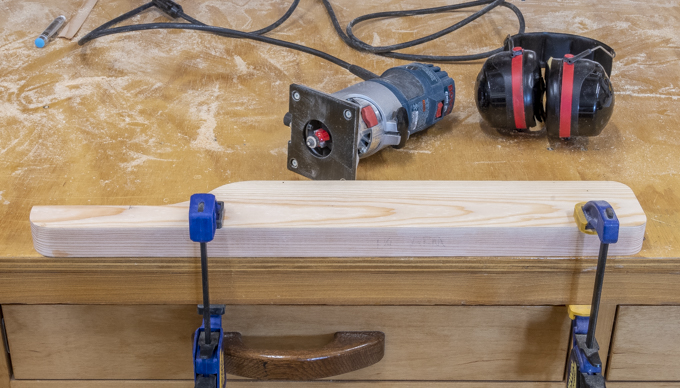
After drilling the angled holes the ends of the long supports get ½” radius rounded corners.  If the piece was shorter the disk sander would be used but as the supports are almost 5’ long they are too awkward to do that.  To make them a high-speed pneumatic die grinder is used to get the rough shape.  That’s followed by a rasp and then a ¼ sheet pad, sander all shown here.  When done I ended up with a nice smooth rounded corner.  The photo shows the tools used and the first one done.

With the edges rounded the long supports get screwed to the braces with 2 ½” long screws.  Here the swing is all put together.  It’s now ready for disassembly so repair of any flaws and final sanding can be done prior to painting.  I wanted to paint all faces of each individual piece so there will be no surfaces exposed to the weather particularly where pieces abut each other.  Also, if all faces are painted then as the wood moves throughout the year due to humidity changes no unfinished spots will show up.  After painting the swing will be reassembled. 

The last thing done before disassembly is to verify the seat height.  This is because my wife is fairly petite and frequently standard depth/height chairs or seats are too high and too deep making them uncomfortable for her to sit in.  Before starting we did some experimenting on the seat depth ending up shortening it by almost 2” from the original plans.  We also made an educated guess on the seat height for material estimating.  Now that the swing is done, we did some actual testing and the seat depth is just right which is good since it’s too late to change that.  However, when we tested the height by adjusting it in roughly ¼” increments it showed our estimation on height was about 1¼” too tall.  Not a big deal but I did have to revise the 3-D drawings accordingly so I would have accurate dimensions to work from. 

Before starting to disassemble the swing, I numbered the slats so they could be put them back on in the same order I took them off.  Other parts that are the same like the seat/back braces also get labeled.

Once the arms and their vertical supports were taken off the screws holding them together were removed, that joint glued and the screws reinstalled.  To hide the screws, I had countersunk them so now face grain plugs are cut using the drill press and a plug cutter.

In this photo the left arm is ready to have the plugs glued in and the right one has its plugs glued in.

Once the glue dried, the plugs were cut off just like the pins in the seat/back braces and trimmed almost flush with a chisel.  Last is to bring the plug flush with a sanding block.  When all done, they are hardly noticeable and when painted probably will be virtually invisible.

Here the swing has been completely disassembled and stacked up ready for me to go over all the pieces and fill any defects that were missed earlier or have shown up then do the final sanding.

Next Up – Painting, Reassembly & Starting End Rails

Monday, April 18, 2022

Porch Swing/Glider - #6 Installing the Slats, Roughing out Parts & Fitting the Arms

The actual installation of the slats starts with one at the front of the seat plus one where the seat and back come together.  After that the second one down from the top gets screwed on.  These three will tie the seat/back braces together square and plumb.  This photo shows the third slat from the top of the back screwed in place at its ends with the center still free to move.  As you can see the slat has a bow that needs to be taken care of.  The bottom left photo is before straightening and the bottom right is where a wedge has been used to take the bow out. 

With the wedge holding the slat straight a screw is driven in to hold it there.  Here is the slat straightened.  The process continues adding one slat at a time straightening as needed.

There are two short slats where the support for the arm and the arm itself get attached to the seat/back braces.  This drawing shows those two slats in blue with the left arm and support removed.  The bottom left photo shows the back slat to be shortened.  It was selected for this location so the knot could be cut off.  The right photo is after it was cut to length.  The short seat slat also had a knot that got cut off.

Work on the top cap is shown in blue in the drawing is next. 

The blank for the cap had flaws on the front left and, on the back, right.   Below the top two photos show the front left before and after cutting the front bevel which got rid of that flaw.  The bottom two photos show the back right before and after where when trimmed to final width the flaw got cut away.

While screwing the slats onto the seat/back braces I noticed that in three places the slats had some knots that ran across the slat and were large enough there was not a lot of material left to provide solid structural support.  Since all the dried material is spoken for and I don’t want to wait several months for more to dry the next option is to take some cutoffs and attach them to the underneath side of the slats to provide for reinforcing and strengthening.  Here are two of them glued with waterproof glue and screwed in place.

With all the slats in place this is what the seat part looks like so far.

With most of the seat done it’s time to layout the rest of the parts and cut them into oversize blanks working around the knots, cracks and so forth.  That took the better part of an afternoon but the real pain was with the twist most of the lumber had developed as it dried.  Some are minor but a couple of pieces took a fair amount of work to flatten.  For me straightening a twisted board is the most time-consuming aggravating problem to take care of.  Doing that, surfacing them to thickness and straightening the edges took the better part of two days.  However, at last all the major part blanks are roughed out.  I hope that the blanks stay flat.  If not, more work will be required.

The next step is to make the arms and their supports.   To verify the measurements a scrap is clamped to the back and a digital level is used to level it.

Laying out the arms is next and the top photo shows that.  As usual there are knots to work around but the layout puts the big one at the top in the waste.  The small one near the right end will go down and not be visible in the finished product.  In the bottom photo the corners and offset area have been rough cut on the bandsaw.  Here a straight edge is clamped to the sander that acts as a guide so I end up with a true edge.

Below the arm is clamped in place with the red arrow pointing to then end point of the round-over.  There is a similar mark on the underside of the arm.  The inset is a closer view of where the round-over ends, everything to the right gets a small radius routed on the edge.

Here is the arm clamped to the workbench along with the router to be used to round-over the edge.  After routing the arms get clamped in place so I can work on their vertical supports. 

Once the vertical support is laid out there is a pretty good size chunk to remove.  The material could be removed with a dado blade but that turns a lot of wood into chips.  An easier way is to start by roughing the waste out on the bandsaw.  That goes quick but leaves a rough irregular surface.  To clean it up the table saw blade is set at the finished cut depth and the rip fence (white fence) set at the notches’ correct width.  Last, a miter fence (black fence) is used to hold the part square to the blade.  To smooth the part is slid left and right across the saw blade then moved forward a little and the left/right pass is repeated.  The process of incremental advancing and side to side movement gives a smooth, true face.

It would be nice if the supports just dropped in place but of course that didn’t happen.  The slat the support abuts to is at an angle so there is a gap at one end.  The bottom photo shows that along with a line parallel to the slat so you can see how much the cut needs to be tapered. 

To cut the taper it’s back to the table saw (top photo) without changing anything except for adding a spacer, in this case some playing cards to move that end of the support out creating an angled cut.  The cards are added one at time until the cut angle matches the slat angle shown in the bottom photo.  I think it took 8 cards to get the right angle shown in the bottom photo.

Because the supports were left a little long cutting them to length is next.  To get the length I could have measured but directly marking is less prone to error especially when the edges are rounded.  Here the left photo shows how a square is used to make sure the support is vertical and a scrap is clamped to the arm to give me the final length.  The right photo is a closer view with the red arrow pointing to the cut line.  After being cut the long vertical edges get routed.

Next Up – Installing the Arms, Testing Seat Height & Disassembly

Monday, April 11, 2022

Porch Swing/Glider - #5 Drilling Slat & Cap Attachment Holes, Testing Slat Layout

Before I start the multi-step process drilling all the mounting holes for the slats a little more layout is required on the seat/back braces.  A center line the length of the braces gets added and last a center line where the slats go gets added.  Rather than measure each slat center line a compass is set for the correct distance and used for marking.  The intersection of those two will be where the screw holes will get drilled.

Below is a section longways through the seat brace.  It shows how the holes are angled so the screws will be square with the slats shown in blue.  Note that the second hole does not have a screw.  That’s because a hole there would exit where one of the two main horizontal supports go.  This means it’s going to be pretty hard to get to the screw if that slat needs to be replaced.  There is a solution and I’ll explain that later.  For now, since the top of the brace is the only place where the holes are located that has to be the starting point.

It all starts by using the center finder in the drill press to adjust the fence so the holes will be dead center in the brace.  At this time, I am not worried about the left/right alignment but just the front/back alignment.

Here is the setup on the drill press for a typical hole.  The angle of the brace has to be adjusted so the centerline of the bit aligns with the centerline of the hole.  This means that every hole except for a few along the back requires a different setup.  To make sure that angle is correct the wood block in front of the brace is used as a reference while the wedge is adjusted until the centerline of the hole is parallel with the block’s edge.

These two photos show different setups on the drill press so the drill is parallel with the screw hole’s drawn centerline.  In the left photo you can see how the block is aligned with the brace’s line while the right photo shows the setup of those holes that are square with the brace. 

In trying to drill the hole where the seat and back meet I ran into a problem with a part of the drill press hitting the edge of the seat brace.  To get around this the fence needed to be skewed at an angle while keeping the bit centered.

One problem with drilling this first set of holes is that the drill is not long enough to go through about half of the holes.  The top photo shows the maximum depth I can drill.  This is a problem since the countersink for the screws needs to be drilled from the bottom of the piece and I don’t know exactly where that is without a hole drilled completely through the brace.   The fix is to use a longer drill bit shown in the bottom photo to finish drilling the hole.  I did not use the long bit in the drill press because it is fairly flexible and could wander off-center.

Now that there is a starting point on the side opposite where the slats will go (bottom) the countersink can be drilled.  Because the screws being used shown in the left photo have a flat bearing face the countersink needs to have a flat bottom which is made with a special bit.  The bits used to make the countersink are the four in the right photo.   The three on the left are used to gradually increase the pilot hole to its final diameter.  The tape on them gives me a depth that’s just short of the final countersink depth.  Graduated bits are used because there is less of a chance of the bit wandering off axis with incremental increases in diameter versus going to the final size in one step.  The fourth bit is a stepped bit with the end the same size as the pilot hole and the larger body made to drill the flat bottom hole needed.

To drill the countersink hole, the seat/back brace is clamped in the vice so the center line of the hole to be drilled is vertical, in this case it’s the one on the far left as shown in the top photo.  The bottom photo shows the completed hole with the step bit in the drill.

Last is to put a screw in and check to see if it sticks out the correct amount.  Just to be safe the stepped drill is initially set a little shallow so most often a small adjustment is needed.  Drilling all the countersinks is not hard but there is just a lot of bit changes since at least half the holes have a different depth countersink so many different setups are needed.

Once all the holes have been drilled and it did take a long time what with all the different setups required it’s time to address the one hole that would have come through at the main brace.  Using the pocket-hole method while not what I wanted to use for all the slat attachments will work here.  This photo shows the jig clamped into place.

In this case a single pocket-hole doesn’t look too bad and will provide access to the slats screw.

One would think that there’s enough holes in the seat/back braces but not quite.  There is an even dozen more holes to be drilled.  Half are used to attach the back cap and the other half are for the front cap.  Here is where those two pieces go.

They are also going to be attached with pocket-holes.  This is the setup used to drill the ones in the seat/back brace for the top cap.  The holes for the front cap are done the same way. 

Finally with all the holes drilled the next step is to route a small radius on the back and bottom edges of the three braces.  Once that’s done the three braces are ready to be used in a test fitting of the slats.

Clamping the braces to the workbench holds them stable while I set some slats in place to see how it will look.  Now some of them have a bit of a curve in but I am sure that they can be pulled into place and held there.

Next Up – Installing the Slats, Roughing out Parts & Fitting the Arms

Monday, April 4, 2022

Porch Swing/Glider - #4 Making Slats & Slat Attachment Options

After an overnight rest none of the pieces showed any real movement so they can be ripped into 15/16” thick slats.  All went well until the last piece, why things seem go wrong on the last piece I’ll never know.  About a foot into the rip a whole lot of internal stress was released and the blank started to really go crazy with one side curving wildly binding the piece in the saw.  I am especially glad my saw has a riving knife that prevents kickback or things could have gotten ugly really, really fast.  After quickly shutting the saw down and prying the piece out I could assess the damage to see if the piece could be salvaged.  Because of the curve there was no way the piece could be cut on the table saw but I could mark a parallel line to the curved edge that’s wider than the finished slat and make that cut on the bandsaw.  The bandsaw cut is smoothed by running the piece through the planer.  The curve is not a problem since the roller pressure in the planer flattens the curve out as the piece gets run through it.  Here is a photo with the curved piece on the bottom set next to a piece with one straight edge on the top.

As there is only one extra slat blank, I decided to try and see if the piece could be salvaged by splicing in a patch.  The top photo has the notched face up in the vise.  On the left is a block set square to the blank where the tablesaw cut stopped.  It will guide the pull saw for a straight and square cut.  The upper right inset is a closer view of that area.  The bottom photo is after the extra material has been cut away with the shoulder plane so there is a flat surface to glue the patch to.

Gluing on a patch with a bunch of clamps is next.  After drying overnight, the clamps are taken off and the patch is easily visible.

Most of the curve is at the end of the piece so when it got cut to rough length that removed the worst part of the curve.  Next a straight slat gets clamped to the patched one and lines drawn on both sides of it to give me a guide to work to.  The bright green area shows the material that has to be removed to make the slat straight with the bottom photo giving a closer view.

A trip to the bandsaw cuts just outside the line getting rid of most of the excess.  That’s followed by using the hand plane to bring the patch down flush with the rest of the slat.  To clean up the other side a few passes through the planer cleans up that bandsawn face making the opposite faces parallel and the correct final thickness.

Cutting all the slats to their final length is done on the chop saw with a stop block is next.  There will be two that are an inch shorter that go between the arms and their supports but they will be pulled from the group later based on any knots or splintering at the ends.  After being cut to length the top of each slat gets all four edges rounded over using a 1/8” radius bit in the router.  If you’re interested the total is almost 90’ of routing.  To speed the routing up some scraps were clamped to the workbench to hold the slats in place during the routing.  The top photo has the router along with the slat’s right end at the bottom of the image.  The bottom photo is the slat’s left end.

Almost all the routing went will although I did have three pieces where the edge splintered a little.  The fix is to glue the splinter back on held in place with masking tape then when dry either route or sand the edge so it’s rounded.  Last is to round the corners at the end of the slat by hand with a sanding block. Here is photo of one of the slats finished end.

Since this project is made from construction lumber it does have knots, cracks, chips and other flaws.  To provide a smooth surface for paint any irregularities need to be filled.  If it were not for the exposure to weather a water-based putty could be used.  However, moisture resistance along with a more durable material is desired so I used a two-part epoxy.  All told only about half of a small package was used so it wasn’t too costly.  When that’s all done here is the stack of slats ready for the next step. 

With the slats done it’s back to working with the seat/back braces.  The cutoffs along with spacers are used to set the slat spacing which ended up being ½” plus the thickness of a playing card.  Here is what the final spacing looks like.  The back layout is next followed by transferring the layout lines to the other seat/back braces.

The back spacing ended up at an even ½”.  Here all that layout is done including transferring the layout lines across all three braces on both the seat and back.

There are a number of ways to fasten the slats to the seat/back brace.  Five were considered and two had partial mockups built:

  1. Installing a wood screw from the top of the slat by countersinking it then filling the countersink with a plug flush to the slat.  Rejected because I want to be able to remove and replace a slat if one breaks plus that’s about a million plugs to make and install.
  2. Installing a stainless-steel flat head wood screw from the top flush with the slat.  Rejected because of aesthetics of all the distracting shiny screws.
  3. Installing a Kreg round head coated weather resistant screw from the top of the slat.  Rejected because of aesthetics and a concern that sitting on all the screw heads would be uncomfortable.
  4. Installing a Kreg round head coated weather resistant screw from underneath using a pocket hole in the seat/back brace then screwing into the underneath side of the slat.  Mockup built.
  5. Installing a Kreg round head screw from underneath by countersinking into the bottom of the seat/back brace then screwing into the slat from the bottom.  Mockup built

Because the braces are curved to make the seat more comfortable both mockups require a screw hole perpendicular to the chord between the edges of the slat.  Those layout lines are added by using one of the slat cutoffs with a guide set on its center line.  It sounds more complicated than it is.  Look at the inset below to see how it all works out.  The main photo shows the two different means of attachment that I had narrowed it down to.  The mockup on the left (option 4) uses the pocket hole jig to make the holes in the side of the brace for the screw while the one on the right (option 5) has the holes on the bottom of the brace.  While the pocket hole method is much easier to do I like the aesthetics of the one on the right.  Mostly because the drilled pocket holes would be visible through the spaces between the slats.

Next Up – Drilling Slat & Cap Attachment Holes, Testing Slat Layout