
After an overnight rest none of the pieces showed any
real movement so they can be ripped into 15/16” thick slats. All went well until the last piece, why
things seem go wrong on the last piece I’ll never know. About a foot into the rip a whole lot of internal
stress was released and the blank started to really go crazy with one side
curving wildly binding the piece in the saw. I am especially glad my saw has a riving
knife that prevents kickback or things could have gotten ugly really, really
fast. After quickly shutting the saw
down and prying the piece out I could assess the damage to see if the piece
could be salvaged. Because of the curve
there was no way the piece could be cut on the table saw but I could mark a
parallel line to the curved edge that’s wider than the finished slat and make
that cut on the bandsaw. The bandsaw cut
is smoothed by running the piece through the planer. The curve is not a problem since the
roller pressure in the planer flattens the curve out as the piece gets run through it. Here is a photo with the curved piece on the
bottom set next to a piece with one straight edge on the top.
As there is only one extra slat blank, I decided to try
and see if the piece could be salvaged by splicing in a patch. The top photo has the notched face up in the
vise. On the left is a block set square
to the blank where the tablesaw cut stopped.
It will guide the pull saw for a straight and square cut. The upper right inset is a closer view of
that area. The bottom photo is after the
extra material has been cut away with the shoulder plane so there is a flat
surface to glue the patch to.
Gluing on a patch with a bunch of clamps is next. After drying overnight, the clamps are taken
off and the patch is easily visible.
Most of the curve is at the end of the piece so when it
got cut to rough length that removed the worst part of the curve. Next a straight slat gets clamped to the
patched one and lines drawn on both sides of it to give me a guide to work
to. The bright green area shows the
material that has to be removed to make the slat straight with the bottom photo
giving a closer view.
A trip to the bandsaw cuts just outside the line getting
rid of most of the excess. That’s
followed by using the hand plane to bring the patch down flush with the rest of
the slat. To clean up the other side a
few passes through the planer cleans up that bandsawn face making the opposite
faces parallel and the correct final thickness.
Cutting all the slats to their final length is done on
the chop saw with a stop block is next.
There will be two that are an inch shorter that go between the arms and
their supports but they will be pulled from the group later based on any knots
or splintering at the ends. After being
cut to length the top of each slat gets all four edges rounded over using a
1/8” radius bit in the router. If you’re
interested the total is almost 90’ of routing.
To speed the routing up some scraps were clamped to the workbench to
hold the slats in place during the routing.
The top photo has the router along with the slat’s right end at the
bottom of the image. The bottom photo is
the slat’s left end.
Almost all the routing went will although I did have
three pieces where the edge splintered a little. The fix is to glue the splinter back on held
in place with masking tape then when dry either route or sand the edge so it’s
rounded. Last is to round the corners at
the end of the slat by hand with a sanding block. Here is photo of one of the
slats finished end.
Since this project is made from construction lumber it
does have knots, cracks, chips and other flaws.
To provide a smooth surface for paint any irregularities need to be
filled. If it were not for the exposure
to weather a water-based putty could be used.
However, moisture resistance along with a more durable material is
desired so I used a two-part epoxy. All
told only about half of a small package was used so it wasn’t too costly. When that’s all done here is the stack of
slats ready for the next step. 
With the slats done it’s back to working with the
seat/back braces. The cutoffs along with
spacers are used to set the slat spacing which ended up being ½” plus the
thickness of a playing card. Here is
what the final spacing looks like. The
back layout is next followed by transferring the layout lines to the other
seat/back braces.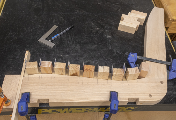
The back spacing ended up at an even ½”. Here all that layout is done including
transferring the layout lines across all three braces on both the seat and
back.
There are a number of ways to fasten the slats to the seat/back brace. Five were considered and two had partial mockups built:
- Installing a wood screw from the top of the slat by countersinking it then filling the countersink with a plug flush to the slat. Rejected because I want to be able to remove and replace a slat if one breaks plus that’s about a million plugs to make and install.
- Installing a stainless-steel flat head wood screw from the top flush with the slat. Rejected because of aesthetics of all the distracting shiny screws.
- Installing a Kreg round head coated weather resistant screw from the top of the slat. Rejected because of aesthetics and a concern that sitting on all the screw heads would be uncomfortable.
- Installing a Kreg round head coated weather resistant screw from underneath using a pocket hole in the seat/back brace then screwing into the underneath side of the slat. Mockup built.
- Installing a Kreg round head screw from underneath by countersinking into the bottom of the seat/back brace then screwing into the slat from the bottom. Mockup built
Because the braces are curved to make the seat more
comfortable both mockups require a screw hole perpendicular to the chord
between the edges of the slat. Those
layout lines are added by using one of the slat cutoffs with a guide set on its
center line. It sounds more complicated
than it is. Look at the inset below to
see how it all works out. The main photo
shows the two different means of attachment that I had narrowed it down
to. The mockup on the left (option 4)
uses the pocket hole jig to make the holes in the side of the brace for the
screw while the one on the right (option 5) has the holes on the bottom of the
brace. While the pocket hole method is
much easier to do I like the aesthetics of the one on the right. Mostly because the drilled pocket holes would
be visible through the spaces between the slats.
Next Up – Drilling Slat & Cap Attachment Holes, Testing Slat Layout
No comments:
Post a Comment