Router Plane

Sunday, October 30, 2016

Dining/Game Table - #11 Inner Rail & Structural Support Assembly

With the MDF securely screwed down I could flip the assembly over and drill the previously started pilot holes for the #8 X 2 ½” screws that will lock this assembly to the inner rails.  This is what I end up with.  There is still work to do on this pilot hole but that will come later.

In Progress Pilot Hole

One of the problems I had was with how to grip the playing surface and lock the structural support to the inner rail.  At first it seemed like I had two mutually exclusive choices:
  1. Have the playing surface and pad gripped enough to hold it in place but not enough to cause it to pucker or wrinkle.  Unfortunately, this left the structural support connection to the inner rail wiggly and not at all solid or secure. 
  2. Mash the pad into oblivion which caused the surface to pucker and wrinkle but did lock the structural support to the inner rail.

After some thought and experimentation I found a way to accomplish both goals, lightly gripping the pad and locking the structural support to the inner rail.  I added small flat head screws to act as spacers between the MDF and the inner rail.  These small screws are located on either side of the large #8 X 2½” screws used to lock the structural support to the inner rail.  By varying the height these small screws are exposed above the MDF allows me to control the amount of compression applied to the playing surface and pad.  It also provides a solid bearing surface between the structural assembly and the inner rail once the large screws are tightened allowing everything to be locked solidly together. 

Here I have temporarily clamped the rough cut inner rail pieces together to form a corner and set them on the small screw spacers.  The large #8 X 2 ½” screws will come up between the small screws.  The gap between the inner rail and the MDF in the photo is 1/8” or half the overall thickness of the pad that probably will be used.  The final gap will be set after I get a sample of the pad and do some testing.

Clamping Gap for Playing Surface

With the locations set and the small screws test fit I took them all out so I could work on the inner rails.  I retrieved the four roughed out pieces, checked them to see if they were all straight, flat and true which they were.  I had run them through the thickness sander using a coarse 120 grit paper so now picked the show face then using 220 grit paper ran them through the sander.  Next was to rip them down to about 1/8” over final width.  Final width will be determined once I have the pad gap set.
Inner Rail Location

Cutting to final length was next.  The inside face of these pieces have a plywood alignment guide fastened to them so they and the playing structural supports are aligned.  When I checked the thickness of the inner rails pieces I found that they were about 1/64” thinner than the structural support pieces.  That’s due to taking the cup out of the original board with the thickness sander. 

What this means is the cross-pieces need to be 1/32” longer than the structural pieces so the inner faces of the inner rail and structural support will align.  The long side inner rails will not change they are the same length as the structural ones.  It also means the effort I had made to make sure and not change the stop I had used on my chop saw to cut the structural cross-pieces to length did me no good.  Oh well, it could have been worse I could have cut the cross-pieces 1/32” too short attached the plywood alignment guides then found that the inner rail assembly was too small. 

With the inner rails cut to length I clamped them in place and screwed them together using #6 x 1½” screws.

Assembling Inner Rail

Once all four corners were screwed together I could work on drilling the final stage of the pilot holes for the large #8 X 2½” screws.  This brings to light the reason I removed the small spacer screws.  The bit I have is just long enough to go through the structural support and the MDF and mark the inner rail.  As shown here 
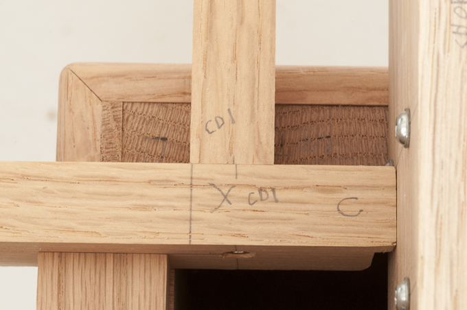
it’s not long enough to drill a full depth pilot hole.   Now with the pilot hole locations marked I could take the clamps off, take the inner rail frame apart and using the drill press finish the last bit of the pilot holes. 
Drill & Screw Lengths 
I want the large #8 X 2½” screws to spin freely in the structural support and the MDF so all the clamping force is generated in the inner rail.  This means I need to go back and enlarge holes in the structural support and MDF before attaching the inner rail.  This drawing shows a before and after of this last bit of drilling.  Note how the pilot hole steps down as it goes into the inner rail.


After reassembling the inner rail, I clamped it in place and at long last I was ready to run the long #8 X 2½” screws in place or nearly so.  Because the small spacer screws are not in place I will hold off screwing them all the way in.  Once I had that done I could take all the #8 X 2½” screws out, remove the inner rail frame, take it apart, notch the ends of the long inner rails to clear the upper screws holding the outer rails to the legs and set the structural assembly back into the table where it goes.  As a safe place to keep them out of harm’s way I just set the inner rails in place where they will go. 

Inner Rail Assembly Set In Place

Once I get the pad and playing surface sample I will do some testing with it to determine the final small spacer screw height and use that to get my final width of the inner rails.


Next Up – Roughing Out Alignment Guide, Test Fit Playing Surface/Pad, Drilling & Assembling Spacer/Inner Rail

Tuesday, October 25, 2016

Dining/Game Table - #10 Building a Flitch Beam & Installing MDF Playing Surface Support

The height of the table is fixed so it is comfortable to sit at, the bottom of the rails are fixed to allow for leg room below and the depth of the playing well is also fixed.  What remains is the depth of the structural support for the playing surface.  The perimeter pieces are screwed to the inner rail which will provide stiffness but the intermediate pieces are on their own.  With a span of 42” and only 1¼” wide they are not stiff enough to provide adequate support for the playing surface to feel solid.  The fix is to borrow a technique from building construction used in the houses, decks, and other wood-frame structures called a “flitch beam”.  It is typically made up of a steel plate sandwiched between two wood beams held together with bolts.  Now I will not be holding up a house but the principal is the same.  I am going to add a 1/8” thick by 1” wide piece of wide aluminum in each of the double cross pieces.  Here is what a completed assembly looks like along with the pieces need to make the second one. 

Flitch Beam & Component Parts
I use 7 screws to hold the assembly together.  Four on one side and three on the other.  Once I have the parts clamped together with the ends squared I laid out the screw locations then drilled a pilot hole down through the aluminum.

Small Pilot Hole

Next is to drill the remainder of the pilot hole and a countersink so the screw will be slightly below the wood surface.
Countersink for Screw

Last is to drive the #6 X 1 ½” flat head screw in. 
Installed Screw

With that done I could start assembling all the individual parts into the structural assembly.  I used a single #6 X 1 ½” screw at each end.  For the pilot holes I drill a small pilot hole then a counter sink and larger pilot hole in the outside piece.  Last is to drive the screw home.  Here is the setup for putting it together.  I have all the pieces held in place with a couple long aluminum clamps and a nylon band clamp.  The pipe clamp on the diagonal is to assure that everything is square and stays that way.  On the left there is a marking gauge, a drill with the pilot hole bit, another drill with the countersink/pilot hole bit and an impact driver for driving the screw in.  The flat plate vice-grip style clamp at the far left front is to assure the top and bottom edges are flush.
Structural Support Assembly

Once I had all the pieces screwed together I set the assembly in the table frame, centered it and cut the first piece of ½” MDF which will provide the base for the playing surface.  This is what that looked like.
Bottom Layer Structural Support in Place

With the MDF in place I did some testing by leaning on the surface to see how much it flexed.  I had hoped that the flitch beam assembly would be rigid enough to help the adjacent cross-pieces resist deflection which they did.  However, it was not enough and that means I will be adding the aluminum bar to the other three intermediate cross-pieces.   The process will be very similar to the three-piece flitch beam I had already built.  I started by laying out the screw locations and using the drill press to drill the pilot holes the aluminum and into the wood.

Setup for Drilling Pilot Holes in Aluminum
Next was to use a drill the same size as the outer diameter of the screw threads for a clearance hole which only goes through the aluminum bar.  Last the screws are installed from the aluminum bar side.  The screws need the underside of the head to be flat so it fully bears against the aluminum bar like the screw on the left.  The one on the right is a typical flat head screw and would not work the way I wanted in this application.

While I had the structural assembly apart I laid out and partially drilled the 22 holes for the screws that will secure the structural assembly to the inner rail.  First was using the drill press drill a pilot hole through the perimeter structural rails then drill the countersink.  When the MDF playing surface support is installed I will extend the pilot hole up through it.  After the inner rail is set in place I will extend the pilot hole up into it.  With that done I will remove the inner rail and drill a clearance hole through the MDF and the structural support.  I know it sounds like a lot to go through but here is what I will end up with.
Section Through Table

Here is how the structural assembly looks with the additional aluminum bars in place.  This time when I stressed the surface it was quite a bit more rigid.
Aluminum Reinforcing in Place

This is what one end of the single cross-piece looks like with the aluminum bar screwed to the cross-piece.
Reference Notes & Aluminum Bar Installed

When all the parts are screwed together I added some more reference notes so I could assemble all the pieces back together in the right place.
More Reference Notes

I could now layout the locations for the screws that will hold the MDF in place.  With all the holes I had already drilled in the structural pieces I needed to make sure these did not conflict with the existing ones.  With the hole locations laid out I could carefully square up the table, clamp the first piece of MDF in place, drill pilot, clearance and countersinks holes for the four screws that will lock that piece in place.  From there I measured the center MDF piece cut it to size then went through the drilling and installing screw routine to lock the second piece in place.  Same procedure for the third and last piece of MDF.  The photo below shows the three pieces of MDF locked in place.

MDF Locked in Place

To  make the installation of the remaining 88 screws easier I moved the assembly out of the table and onto my work bench where I could work at a comfortable height.
Installation of Screws thru MDF in Progress


Next Up – Inner Rail & Structural Support Assembly

Monday, October 17, 2016

Dining/Game Table - #9 Installing the Remaining Rails & Starting Playing Surface Structure

With the first leg in place I moved on to mounting the rest of the rails to the legs.  I could have stood the legs on the floor holding them in place with one hand on each, balance the rails in place with another hand, square the leg to the rail with a couple more hands and with my other two hands put on the clamps so I could drive the screws in.  As near as I can count that means I need to be at least an octopus.   A better alternative is to locate, square, clamp and screw in place the other leg while it is lying flat on the work bench.  From there I could balance the side rails vertically, square them, attach a clamp then screw them in place with just two hands. 
Attaching Rails to Legs
Next was to remove the side rails and set the first leg/long rail/leg sub-assembly aside.  I went through the same process with the other long rail and the two previously mounted side rails.  I took the side rails off the first sub-assembly and mounted them to the second sub-assembly for a reason.  When I go to put all the pieces together I don’t have to be as precise as when I put it together the first time.  I can just screw the side rails into place using the previously made holes.  That way as I tighten the screws down the rails and legs are going back exactly where they were when I had it flat on the bench squaring everything in the process.
All 4 Legs Attached


When all done this is what the leg to rail connection looks like. 
 
Leg to Rail Attachment
With the legs and rails together I could start on the support structure for the playing surface.  Another discussion with my son has reduced the playing surface down to two options.  The only real difference is a thickness variation of 1 mm.  Now I could work out the final details of how the playing surface structural support, outer rails, interior rails and the top arm rest would all tie together.  Four designs and three prototypes later I believe I have all the details worked out.  For now this is a section showing how all the components fit together.  There are quite a few screws that hold the parts together and I will get into them later as the pieces go together.
 
Table Section

With the design done I can begin working my up from the bottom of the structural support.  Here are the pieces that form the first layer, I will start with them. 
Structural Base Layer

First, I went through my stack of oak looking for a couple of pieces that were the ugliest.  Since these are under the table hidden from sight.  They needed to be structurally sound but do not need to look quite as nice as the ones exposed to view.   After laying out the needed pieces I cut the boards to length and checked for a good edge.  Straight and true does not describe what I had to work with.  The top part of the photo below shows the piece in the routing jig I use to cut a straight edge and the three bottom images show a close-up of the ends and center.  There is more than a 3/16” curve to this edge I needed to take out. 
Straightening Curved Edge

With the piece clamped in place I just had to run the router along the edge using the square tube as a guide.  Talk about a bad hair day!
 

Once done I have a clean, straight and true edge to work with.
 
Straight Edge
Using that straight edge I cut the needed pieces about 1/8” wider than the final width.  As I was cutting the last piece I noticed that there must have been some internal tension as the saw kerf started getting wider and wider the farther I cut through the piece.  Sure enough when I had completed the cut I had a piece with a nice curve to it.  Now seemed like a good time to quit for the day so I set all the pieces aside to see if any of the others were going to move around on me.  The next day I found two pieces had problems.  Easy fix, since I had cut the pieces slightly wider that the finished dimension.  I just set them in the routing jig I had used, cut a new straight edge then ripped all the parts to their final width.
 
Structural Support Pieces
Next is to cut the long side pieces to their final length and set them in place.  I then marked the ends for a notch that allows for clearance of a screw head that holds the end rail to the leg.  When I laid out the location of these screws I could have offset this one but decided to go with a location that gave me maximum leg to rail joint strength.
 
Structural Support & Screw Conflict 
I cut the notch on the table saw using a regular blade, a stop block and making two passes.
 
Cutting Notch
I could have used the dado blade to make the cut but would have spent more time doing the setup than taking two passes to make each of the four notches.  Here is what the notched piece looks like just set in place.
 
Finished Notch in Structural Support
With the long rails done I could run all the pieces through the thickness sander to clean up the scallops from the planer and give me a smooth surface.  I could have left them as-is because these are out of sight but I would know they were rough and I wanted to do it right.   Following that I cut the cross rails to length and temporarily clamped everything in place. 
 
Base Structural Layer in Place
You would think that assembling these pieces to form the support structure would be next but there is one more thing to deal with before I do that.


Next Up – Building a Flitch Beam & Installing MDF Playing Surface Support

Monday, October 10, 2016

Dining/Game Table - #8 Design Discussions, Humidity Driven Expansion & Contraction, Attaching First Rail to Leg

In between the woodworking I did three more stain samples.  We seem to have the color right but it is still a bit light.  For these samples I increased the dye to alcohol ratio by 50% and by 100% on the closest mix and by 50% on the second closest.  The results are not quite what I thought they would be in that doubling the amount of dye in the solution did not look to have a corresponding darkening effect.  I may be reaching the limit of the dyes.  I could add black but think that would screw up the color.  Once my son gets the samples we will discuss and see if one of the samples will work.

Stain Tests


In  the beginning we started with a poker table playing surface.  In time the view of the playing surface function has evolved and so has the specifications.  Board game tables and poker tables have two slightly different criteria and since this is primarily going be a board game table that is what we will focus on.  Our criteria boiled down to these items: 
  1. A slick smooth surface is not desirable, something with a little tooth is preferable.  More toward a pool table felt rather than the casino speed cloth. 
  2. Something that will not permanently deform when loaded and left for a week (long term game or weekend to weekend playing).  The pad needs a memory to spring back to original flat surface.
  3. The pad needs to be flexible enough to deform when pushed with your finger to allow pick-up of items but not so soft as to deform when you have stack of tokens on it.
  4. A closed cell material is preferable to an open cell so that it will not absorb anything spilled on it.
  5. The playing surface needs to be cleanable to remove the inevitable soiling.
  6. The playing surface and underlying pad need to be replaceable at a later date. 

 As I told my son when we started, with custom furniture the good news is you can have whatever you want.  The bad news is you can have whatever you want, but you have to decide exactly you want.  I think he has sorted through the myriad of options for the pad/playing surface and is close to a decision.  I include our discussion because the pad and playing surface will drive the final design of the support structure for the playing surface.  It’s not critical in the sequence of construction, at least not for a couple of weeks.  Here is one of two generic support assemblies I am considering using.

Possible Structural Playing Surface Support System

After letting the table rails set for a few days I checked them and good news they were flat and straight.  The flattened cupped pieces for the arm rest are flat but I want to give them plenty of time to make sure they are stable. 

I have given the connection between the legs and the rails quite a bit of thought because there can be a lot of stress on that joint.  The simplest way would be to glue the leg to the rail and reinforce with 4 or 5 wood screws.  Given the size of the rail and the leg I would have a little over 14 square inches of glue area and that’s quite a bit.  Adding wood screws to reinforce the joint would make it really strong.  Unfortunately, that approach ignores that the grain in the leg runs one way and the grain in the rail is 90 degrees to that.  I am concerned with the cross grain expansion and contraction due to humidity changes.  I have seen all sorts of examples in antiques where humidity driven width changes causes table tops to split, chest of drawers sides to split, trim that works loose and other problems where two pieces of wood fight each other and eventually one splits, breaks or comes loose.

Rather than be in the dark and make a guess on the amount of expansion I did some research and found that the potential expansion with the humidity difference between New Mexico and Arkansas could be almost 1/8” across the 3¾” rail to leg connection.  I know from sad experience what building something in the dry desert and taking it to a more humid location can do.  Once about 6 months after I delivered a hall cabinet to Arkansas one set of doors would not close.  I had the tolerances a little too tight and in the summer humidity there it grew just enough to not close.  It really surprised me as there was only about 2” of cross grain wood in each of the door stiles.  Anyway, I had to take the door back to New Mexico, trim a sixteenth off one edge and refinish.   No problem since then.  Now I know that with 4 stiles the total movement could be about an 1/8”.

After a lot of thought I decided to limit the glue area to a 2” square patch in the center of the connection leaving the rest of the joint freedom to move with humidity changes.  This will limit movement change to less than 1/16”.  I will also add 4 wood screws between the leg and each rail.  This should give me a pretty strong joint.
Layout of Screw Locations for Leg to Rail Connection

Now that I had decided what to do I just had to cut the rails to the correct width and length then lay out where the screws and the glue will go.  To reduce the chance of errors and speed things up I use a couple of marking gauges and adjustable squares set to the distances I needed.  Using them all the layout lines end up the same.

Layout Tools

Because the project will be broken down flat for delivery I mark which piece is which along with reference notes so when I go to put it together I put the right piece in the right place.

Reference Noted & Marked Screw Locations

Next step is to drill pilot holes for the screws, square the leg to the rail and clamp them together.
Drilled Screw Holes & Squaring Legs to Rail

In  the image below you can see the screw that I will use.  It is a round head Kreg® pocket screw.  The small block of wood is the same thickness as the rail.  It’s always good to check screw length because driving a too long screw and having it come out the exposed side is not a good plan.  I use the Kreg® screws because they have a round head with a flat bearing surface against the wood.  Combined with an oversized pilot hole that allows the wood to move around the screw.  A flat head screw’s conical head can lock the pieces in place restricting movement.  It can also act like a wedge and split the wood if you are close to the edge.  Since I had that situation in a few places I wanted to minimize the risk.  On the left side of the leg the square is where the glue will go during final assembly. 

Ready to Install Screws

Once the screws are driven home the connection between this long rail and leg is solid.  I am not worried about the screws and glue holding the eventual dining table load since the rails are supported by the leg.
Rail Screwed to Leg


Next Up – Installing the Remaining Rails & Starting Playing Surface Structure

Monday, October 3, 2016

Dining/Game Table - #7 Banding/Leg Intersection & Roughing out Top Pieces

With the banding done I can now go back and clean up the round over/banding intersection.  As I said before this is all done with hand tools like a rasp, file and sandpaper.  
Before & After Closeup of  Leg Roundover Blending

Not hard, just time consuming since there are 44 of them to do.  It takes about 45 minutes per leg to do all the cleanup and blending.

Before & After of Leg Roundover Blending

The legs are nearly done, just the applique pieces need to be added but that won’t happen until much later in the process.  Since they are stained with a different mix I will need to do the legs first then apply the applique pieces.

Completed Legs


Leg Applique Size Testing
Because I had changed the size of the banding I thought that I might need to change the size of the applique pieces on the legs.  The best way to see is to cut a test applique piece and tape it to the leg to see how it looks.   The right leg has the piece sized per the drawing.  The left one is just 1/8” thinner at 1¾” wide.  Not much, but the devil is in the details.  I looked at it set on the workbench at eye level and setting on the floor as you would normally see it.  Consensus is that the narrower piece looked more in scale and like an accent.  The right one just seemed a little too bulky.  Surprisingly the height did not change from the drawing even though I had made the bands wider.  It looks good here and even better when on the floor.  Setting it on the floor changes the perspective in that it clips the distance between the top band and the applique due to the ½” band thickness

With the size decision made I took the random width applique pieces, ripped them all to a constant slightly oversize width and ran them through the thickness sander again using a fairly fine 220 grit abrasive.  While none of the pieces had gone really crazy there was some minor cupping in a few.  So with everything now flat I stickered them for air flow and set them aside to see what happens.

Rough Cut Applique Pieces

Next is to select the material for the four aprons.  I found a single board that I can get all four pieces out of and have very little waste.  Fortunately, the knot holes at the right end are outside the area that I need. 

Apron Layout

I started out by rough cutting the board to length about an inch long then ripping those pieces to about ¼” too wide.  I let them set overnight to see if they are stable.  The next day I ran them through the thickness sander to flatten and get rid of the planer scallops.  With that done I set them where they go in each leg.  This gives me an idea of what the table will look like.  Fortunately, I had two left and two right legs – they are mirror copies of each other.  I know it sounds silly but it can happen that you end up with 3 left legs and one right.

Test Fit of Table Rails

While the side rails are stabilizing I pulled out some more oak for the top arm rest picture frame and the 4 pieces that will form the sides of the well leading down to the playing surface. 


A little creative layout got the pieces I needed out of a couple of boards. 


When I went to cut one of the boards to rough length I noticed that it looked cupped.  Setting a straight edge across the piece confirmed my suspicions.  Actually it was not any great feat of observation as the board was cupped almost 1/8”. 

Cupped Board Inner Rail Board

Since I was going to rip it into narrower pieces I was not too concerned so I went ahead, made my rough cuts to length then ripped to rough width.  With that done I set the straight edge on the ripped narrower pieces and found the cup had been reduced to less than 1/16”. 

Rough Ripped Inner Rail

That small amount I can take out with the thickness sander and at the same time remove the planer scallops. 

Inner Rail After Flattening

When ripping boards to width sometimes the cutoff piece on the outboard side of the saw blade right at the end of the cut will end up with a little bump as shown below.  They are not always this big but frequently they are there. 

Cutoff Piece with End Nib

If  the piece is scrap, then it’s no problem.  However, if you are going to use that edge against the rip fence to cut another piece then it’s a problem.  As you make that next cut everything will go smooth until that bump hits the back edge of the fence and that’s not good.  If it’s big then it can stop your forward progress leaving you holding the board with the saw running and no real option except to turn the saw off, wait for the blade to stop, remove the board, get rid of the bump and recut the piece.  If it’s a small bump it can cause worse problems in that it can cause the board to shift toward the blade allowing the bump to continue on down the fence face and giving you a taper the width of the bump from the point it hits the fence until you finish the cut.  Now instead of parallel edges you have a taper at one end.   For my saw I would have the last 18 inches of the cut tapered.  Imagine if you are trying to glue up pieces for a table top with one tapered end.  You end up with gaposis and bad words being used.  The cure is to keep an eye on the cutoff and if there is a bump get rid of it.  I use a knife or a scrap block with some 120 grit sandpaper fastened to it with spray adhesive.

End Nib Removed & Sanding Block

With these parts cut it pretty much completes the rough cut work for the exposed oak.  There is still the structure and interior bracing needed to support the sunken playing surface.  For now, I am going to let the rough cut pieces set and see if they are stable.  I will pay particular attention to the cupped pieces to see if they are done moving around.

Rough Cut Parts


Next Up – Design Discussions, Humidity Driven Expansion & Contraction, Attaching First Rail to Leg