Router Plane

Monday, March 25, 2024

Wastebasket – #8 Filling a Flaw, Assembly & Finishing

When the original panel was assembled there was a knot and some pitch pockets on the inside faces.  The pitch pockets were caused by a feeding insect or some damage that created a cavity in the tree.  As the tree continues to grow the damage gets filled by sap resulting in a resin filled pocket.  The other side of these pieces are the exposed visible faces and do not have the pockets.   While these are the inside of the wastebasket I want to do a little repair for cosmetic reasons.

First, using an X-ACTO knife the pitch and loose bark gets cleaned out.  Filling the resulting void is next.  In the past I have used black or amber epoxy or as in this case sawdust collected from sanding the 
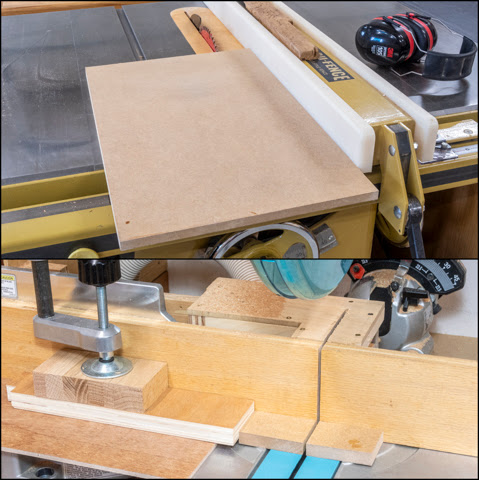
piece that will be combined with the finish to create a filler.  In the top photo the block in the upper center has a little finish poured on it that gets dribbled next to and into the cleaned-out pocket.  The putty knife is then used to make a slurry with the sawdust which gets packed in the pocket (lower left photo).  Any excess is wiped off and left to dry.  After the finish has cured overnight the surface gets sanded smooth leaving just the dried mix of sawdust and finish (lower right photo). 

With the pitch pockets filled I can do the final steps before gluing the pieces together.  When the cedar wastebasket got glued together cleaning up the glue that got squeezed out on the inside was a pain.  To make it a little easier the inside faces are getting prefinished with four coats of finish on the surfaces that will not get glued together.  Keeping the finish off the glue surfaces is done using blue painter’s tape.  In the top photo below, you can see it applied along the long edges where the box joints are.  There is also a ½” wide strip of tape along the bottom edge.  This is where the pieces will get glued on that support the bottom.  The bottom photo is after applying the finish, with the tape removed and in the order they will get glued together.

This is a closer view of the worst of the filled in pitch pockets.  It shows how using finish and sawdust can make a patch that looks natural and blends in.

This is a photo of the inside of one corner’s dry fit.  It’s included to show how the grain flows from one piece to another, a view that won’t be available when all four side are glued up.  Also, when glued and clamped tightly together the whiteish line of unfinished cherry at the corner between the pieces will not be there.

From here the process of gluing the sides together, adding the bottom braces then fitting and gluing the bottom in is done the same way as with the cedar test piece.  Once glued the tiny protrusion of the box joints is sanded flush and everything is given a final sanding with 320 grit sandpaper.  For protection four coats of wipe-on polyurethane finish is applied.  After applying the final coat and giving the pieces several days to cure and harden both the inside and outside get wet sanded starting with 2,400 grit then working through the grits ending up with 12,000.  Here are the completed Cedar and Cherry finished pieces.  I am really happy with the way they came out, it’s a rather simple looking design that had a fair amount of work to make it happen.  The cherry one goes in the den as a matching piece to the computer desk and credenza while, for now, the cedar one sits to one side in the shop.

The jig gets set alongside the other jigs and fixtures I have made ready to be used as needed.  Truthfully there was no economic benefit to making the wastebasket over getting a plastic one but it sure was a lot more fun!

Monday, March 18, 2024

Wastebasket – #7 Glueup, Bottom, Finishing & Starting on Actual Wastebasket

At this point it’s time to start the glue up.  After some thought I was pretty sure that if I tried to glue up all four corner joints at once it would be a problem.  Because there are so many different surfaces in the box joints, I was afraid the glue would start to set up before I could get it assembled and clamped.  To reduce that possibility only two corners will be done at a time.  Somewhere in the forest of clamps below is the wastebasket.  This just goes to show the old saying of, “You can never have too many clamps.” is really true.

After gluing the other two corners together and letting the clamped assembly cure overnight here is the end result.  The photo on the right is a close view of the glued corner in it you can see the slight bit the pins and tails extend.  That’s because it’s easier to sand them flush versus trying to bring the whole face down flush.  For the real wastebasket I will reduce the depth of cut just a little so I don’t have so much to remove to bring the joints flush.

Bringing them flush is done using a random orbital sander with a 60-grit sanding disk to carefully sand them just flush.  The sanding disk then gets changed to a finer 120-grit disk and the whole surface is sanded smooth.  The bottom photo is a closer view of the finished surface. 

Making and installing the supports for the bottom are next and are made from leftover pieces of cedar.  The top edge gets an angle cut to match the slant of the of sides so the bottom lays flat on them.  That’s easy since the table saw still has that angle set on it.  Next, they get cut to about ¼” square.  To mark their length a sharp marking gauge is used.  That’s shown in the photos below.  Once cut they get glued in place and nailed using a 22-gauge pin nailer.

The bottom is cut from a piece of ¼” oak veneered plywood with the edges beveled to fit the tapered sides.  This is what that looks like from the bottom and while the plywood looks pretty bad, which it is, that’s because this leftover only had one good veneered face and that’s on the inside.  

The bottom is installed next by applying a thin bead of glue on the supports.  Clamping it in place while the glue cures is shown in the photo below.  No mechanical fasteners here.  Actually, the only mechanical fastening in the whole piece are the pin nails used to hold the supports in place while their glue dries.

Once the bottom is installed final sanding is done which includes softening all of the sharp corners with a sanding block and hand sanding.  The left photo shows the wastebasket done and ready to finish.  I had not planned on putting on a finish this piece because I anticipated more problems in getting the jig to work and thought the test pieces would get used up solving problems in the build.  That was not the case so it’s going to get a finish which will be four coats of Watco Danish Oil finish.  Since the cedar is a soft wood, I think that it will get dinged up over the years and this type of finish is easily reparable.  The oil also results in a nice warm color as shown in the right photo.

At this point the testing is done and I can start on the actual wastebasket to be made out of cherry.  This build will follow the same process as the test piece so going through the whole process would be redundant.  My plans are to take occasional photos along the way at various milestones to let everyone know how it’s going.

Here in the top photo the cherry has been ripped to ½” thickness with all three pieces glued and clamped together.  The photo on the right shows a straight ruler being used to check and make sure the glued-up boards are flat and not bowed.  If there were a bow light would be visible under the ruler.  The bottom photo is after the panel has been squared up, trimmed to width and sanded with 220 grit.

All went well with cutting the individual tapered panels to size.  Using the jig to cut the box joints also went well or at least I thought it did until the first test assembly.  For some reason two of the box joints in two panels were not cut to the correct depth and are about 1/32” too shallow.  I have no idea why since they were all cut with the same setup plus the ones on either side were fine.   I suppose that’s better than being too deep since the fix is to recut those to the proper depth.  The problem is getting the pieces back exactly where they were in the jig to begin with because if the alignment isn’t perfect the joint is going to be cut too wide and there will be a gap.  Ordinarily with non-tapered pieces this would be easy, just butt the piece up against the reference board.  However, with the taper when the first joint is cut a little bit of the reference point gets cut off.  This photo shows the gap with the piece correctly aligned.

To get the alignment rather than eyeball the location I used the original spacer (red arrow, bottom photo) when the location was set for the Vertical Indexer.  With the spacer in the slot cut by the dado blade the piece is set tight to it and clamped in place.

With everything set the first pass of recutting the joint is made.  Here the red arrow points to where the cut was made just a little bit deeper.  After both of the joints were recut when the wastebasket was reassembled for another test fit everything fit together just right.  I would note that the depth of cut made by the blade was not changed for the recut.

Next Up – Filling a Flaw, Assembly & Finishing

Monday, March 11, 2024

Wastebasket - #6 Jig Testing & Making Prototype

To make the tapered sides I decided to use a wedge cut with the desired ¾” over 12” taper.  The wedge gets laid out on a piece of plywood then clamped into the chop saw.  To align, the layout line is adjusted until the blade follows it as I run it in and out along its cutting path.  The top photo shows where the blade will cut along the line and the bottom photo shows the completed cut.  Not shown in the bottom photo to stabilize the plywood is a small wedge out of sight between the plywood and the chop saw’s fence.

Since I don’t need the first set of box joint tests those pieces will get tapered and used for the next test.  To make the taper the wedge is clamped to the chop saw’s table and the old test blank is set in place to cut.  I did make a layout line to assure that I ended up with a tapered piece rather than a parallelogram.

Because I do not want all the box joints to be the same size one setting of the jig’s Spacers won’t work.   There has to be one setup for the sides and a different one for the ends.  After resetting the Spacers for the first cut while I was tightening the Locking Handle the whole Spacer stack shifted a bit.   Some experimentation led me to believe the single Locking Handle did not apply equal pressure.  Adding a second one corrected the problem.  While I was at it, I changed the Locking Handle to thumb screws.  The photos below the revisions. 

Each of the photos below show a finished piece and the Spacers setup required to make the cuts.  The left photo shows the setup for the ends.  Note how the first spacer is up, the next is down then a repeating pattern of two up and one down.  The right photo shows the setup for the sides.  Here this first spacer is down, the next one up then a repeating pattern of two down and one up.  The good news is that I can cut both ends or both sides at once.

Here is what the assembled test piece looks like dry fitted.  All the joints came out just right and I am happy with the way it looks.

Now it’s time to start on a full-size prototype using the cedar blank I had glued up some weeks ago.  After squaring the edges and trimming it to its final width I can start cutting out blanks for the sides and ends.  The tapered wedge from earlier is put against the base of the cutoff sled shown here at the right.  The panel is set tight up to it then another tapered wedge cut at the same angle is butted up against the panel to provide a parallel surface to clamp to.  All three pieces are clamped together so nothing moves during the cutting process.  The black line is my reference to make sure I cut the panel as intended.

Next is to reset the blank and the wedges to cut the first side along with the second taper.  The piece is cut about an eighth of an inch long for trimming later.  Once both sides are cut, they will both be cut to final length at the same time so they are a perfect match.

Cutting the first end is next.  So, the grain and color of the boards that make up the panel run around the finished wastebasket the just cut tapered edge needs to be cut off and a new one cut facing the right direction made. 

Cutting the end to length and tapering follows.  Just like the side it’s cut a little long to be recut later.

The process is repeated to cut one more side and one more end.  When that’s done the matching pieces are put back in the sled then both cut at once so they are the same exact size.  Here are all four pieces tapered and sized ready to start cutting the box joints.  Here you can see how the grain flows from one piece to the next.

With the side and end pieces tapered cutting the box joints is next.  I am going to start with the ends first.  Here is a photo of how the Spacers are set for them.  To help me make sure that I get the spacer pattern correct the test side is used as a guide to get started.  That piece is shown in front of the actual side.  Once I am satisfied that the pattern is correct the dado stack set to the correct cut depth of just a tiny bit deeper than the end’s thickness.  With that done both ends get clamped into the jig and the cutting begins following the same procedure as the test.  If you are wondering what the blue tape is for on the jig it acts as a reference as to how far I need to make the cuts.

Here is the jig set up to cut the sides where the vertical Spacers have been laid down and the horizontal spacers have been rotated upright.  From here the sides are clamped in place and cut just like the ends above.

Once the sides are cut the four pieces can be dry fitted together and this is what that looks like.  At this point the only thing holding the pieces together is the friction fit of the box joints.  Earlier on I described the process when cutting the side and end blanks to their tapered shape so the color and grain would flow around the assembled piece.  Now you can see the end results of that work.

Before I start to glue the pieces together there is one last bit of work to do.  The drawing below shows the wastebasket with the end removed to show the how the sides taper outward.  This tapering causes the top and bottom edges to not be parallel to the floor which is what I want.  That means the blue areas in the drawings on the right at the top and bottom need to be trimmed off.

This is done at the table saw but first I need to set the blade to the correct angle using a sliding T-bevel set against the side to get the angle.  The blade is then tilted to match that angle.

The photo on the left is the bottom before trimming.  The red arrow shows the bit that needs to be cut off.  When making this cut, I trimmed off a little more than needed to get rid of the little sliver.  The finished cuts are shown at the right.  Now the wastebasket will sit flat on the floor.

Next Up – Glueup, Bottom, Finishing & Starting on Actual Wastebasket

Monday, March 4, 2024

Wastebasket – #5 Index Guide & Jig Testing

Probably the most critical item in the jig is the Index Guide or bolt.  The diameter of the bolt that interacts with the jig has to match the thickness of the saw cut.  It’s this match that allows the jig to make perfectly matching box joints.  Now the dado blade setup has two stacked 1/8” blades for  ¼” plus a .004” spacer totaling .254” so the bolt diameter that works the jig needs to be that.  Fine tuning will come later after the first test cut.  This means the 5/16” diameter bolt needs about the last half inch or so thinned down to match the thickness of the dado stack.  You would think that would be the dado thickness of ¼” plus .004” or .254”.  Not so, when I cut a wood spacer to fit the cut the dado stack made it came to be .247” so that’s what I need.  As a side note my guess is over the years when I have had the blades sharpened it may have reduced the total width of the cut some.  Anyway, the left photo is the bolt ready to go in my lathe chuck so I could file it down to the desired diameter.  The three nuts on the bolt will help keep it stable in the chuck.  The right photo is after it has been filed down to .248” which is a little large but that’s my starting point for testing.  The two extra nuts on the bolt in the right photo are my stop to keep from filing too far up the bolt.

Installing the bolt in the Moving Indexer is next.  In these photos the bolt has been run in with the lock washer and nut installed. 

The redesign in going from the wood spacer to the bolt requires one more change.  Since the nut is a larger diameter than the bolt, I need to cut a clearance notch in the upper right part of the right corner of the Side Brace piece.  The top and the lower left photos show the notch where I used a Japanese pull saw to make the relief cuts.  The lower right photo shows the finished notch after the waste was removed and the bottom cleaned up.

With the notch completed the Moving Indexer assembly is put back on the jig and slid all the way to the right until the bolt contacts the right Side Brace.  The two photos show clearance around the nut from the both inside and outside the jig. 

Cutting all 53 Spacers for jig is next.  The top drawing shows what I think their setup will be for cutting alternating ½” and 1” finger joints.  The middle photo has all of them cut and ready to go into the jig.  The bottom photo has the Spacers in the jig for even ½” joints which is what I will start testing with.

Actually, cutting the Spacers is straightforward.  A piece of ½” thick MDF is cut into strips using the table saw as in the top photo.  They are then cut to length using the chop saw with a stop set shown in the bottom photo.

Next is to install the stack dado and start the calibration of the jig.  Below are the left and right 1/8” thick outer blades of the 8” dado.  Also shown are two of the ten shims in several sizes that can go between the blades to fine tune the width of the cut.  The top one is .004” thick and the bottom one is .020” thick.  Here I will only be using the .004” one.

The last piece is to be installed is the Vertical Indexer (red arrow).  To locate it the bolt in the Moving Indexer is pushed up against jig’s right Side Brace (left bottom photo).  A spacer the thickness of the blade stack (.247”) is inserted in the slot it cut in the jig’s Base then the Vertical Indexer is set against it and screwed in place making sure it’s square to the base (right bottom photo).

At long last I can make my first test cut.  With the blade set so it is the thickness of the stock above the top of the Base plus a little or in this case since the test piece is ½” thick the blade is set about 17/32” above the top of the base.  Once that’s done two test pieces are clamped in the jig with one offset the thickness of the one of the spare Finger Spacers used identified by the red arrow. 

With the bolt up against the right Side Brace the first pass using the dado set is made as in the top two photos.  Next, the Moving Backer assembly is moved so the bolt is tight to the left side of the gap and a second pass through the dado set is made shown in the bottom photos. 

To make the next cut the Moving Backer assembly is picked up and the bolt set one space over to the left per the top two photos.  The same process as above is used to make this set of cuts.  To make the remainder of the joints the process of moving the Moving Backer assembly over one space at a time then making the cuts is repeated until the whole edge is done.  The bottom photo shows the completed pair of test pieces.

After removing the pieces from the jig here is the test fit which to my extreme surprise fit perfectly.  Just snug enough to gently fit together without being loose.  No adjustment was needed but if it were here is how that works.  If the fit is too tight then the Index Guide in my case the bolt would have to be made thicker or the dado blade stack thinner which is why I added the .004” shim to the stack so there was an easy way to make the stack thinner.  On the other hand, if the fit is too loose then the bolt would need to be made thinner or the dado stack made thicker by adding another or different sized shim.

One other addition after I started cutting was to add a stop block (red arrow) clamped to the table saw’s rip fence.  It is set so I make the full depth cut but prevents me from sawing too far into the jig keeping the blade safely buried in the Spacer Base.

Next is to try and make a small-scale version of the wastebasket to test out how tapered sides work while using alternating ½” and 1” box joints instead of all ½” joints like the just completed test.

Next Up – Jig Testing & Making Prototype