
Probably the most critical item in the jig is the Index
Guide or bolt. The diameter of the bolt
that interacts with the jig has to match the thickness of the saw cut. It’s this match that allows the jig to make
perfectly matching box joints. Now the
dado blade setup has two stacked 1/8” blades for ¼” plus a .004” spacer totaling .254” so the
bolt diameter that works the jig needs to be that. Fine tuning will come later after the first
test cut. This means the 5/16” diameter
bolt needs about the last half inch or so thinned down to match the thickness
of the dado stack. You would think that
would be the dado thickness of ¼” plus .004” or .254”. Not so, when I cut a wood spacer to fit the
cut the dado stack made it came to be .247” so that’s what I need. As a side note my guess is over the years
when I have had the blades sharpened it may have reduced the total width of the
cut some. Anyway, the left photo is the
bolt ready to go in my lathe chuck so I could file it down to the desired
diameter. The three nuts on the bolt
will help keep it stable in the chuck.
The right photo is after it has been filed down to .248” which is a
little large but that’s my starting point for testing. The two extra nuts on the bolt in the right
photo are my stop to keep from filing too far up the bolt.
Installing the bolt in the Moving Indexer is next. In these photos the bolt has been run in with
the lock washer and nut installed. 
The redesign in going from the wood spacer to the bolt
requires one more change. Since the nut
is a larger diameter than the bolt, I need to cut a clearance notch in the
upper right part of the right corner of the Side Brace piece. The top and the lower left photos show the
notch where I used a Japanese pull saw to make the relief cuts. The lower right photo shows the finished
notch after the waste was removed and the bottom cleaned up.
With the notch completed the Moving Indexer assembly is
put back on the jig and slid all the way to the right until the bolt contacts
the right Side Brace. The two photos
show clearance around the nut from the both inside and outside the jig.
Cutting all 53 Spacers for jig is next. The top drawing shows what I think their
setup will be for cutting alternating ½” and 1” finger joints. The middle photo has all of them cut and
ready to go into the jig. The bottom
photo has the Spacers in the jig for even ½” joints which is what I will start
testing with.
Actually, cutting the Spacers is straightforward. A piece of ½” thick MDF is cut into strips
using the table saw as in the top photo.
They are then cut to length using the chop saw with a stop set shown in
the bottom photo.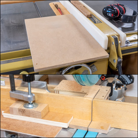
Next is to install the stack dado and start the
calibration of the jig. Below are the
left and right 1/8” thick outer blades of the 8” dado. Also shown are two of the ten shims in
several sizes that can go between the blades to fine tune the width of the
cut. The top one is .004” thick and the
bottom one is .020” thick. Here I will
only be using the .004” one.
The last piece is to be installed is the Vertical Indexer
(red arrow). To locate it the bolt in
the Moving Indexer is pushed up against jig’s right Side Brace (left bottom
photo). A spacer the thickness of the
blade stack (.247”) is inserted in the slot it cut in the jig’s Base then the
Vertical Indexer is set against it and screwed in place making sure it’s square
to the base (right bottom photo).
At long last I can make my first test cut. With the blade set so it is the thickness of
the stock above the top of the Base plus a little or in this case since the
test piece is ½” thick the blade is set about 17/32” above the top of the
base. Once that’s done two test pieces
are clamped in the jig with one offset the thickness of the one of the spare
Finger Spacers used identified by the red arrow. 

To make the next cut the Moving Backer assembly is picked
up and the bolt set one space over to the left per the top two photos. The same process as above is used to make
this set of cuts. To make the remainder
of the joints the process of moving the Moving Backer assembly over one space
at a time then making the cuts is repeated until the whole edge is done. The bottom photo shows the completed pair of
test pieces.

One other addition after I started cutting was to add a
stop block (red arrow) clamped to the table saw’s rip fence. It is set so I make the full depth cut but
prevents me from sawing too far into the jig keeping the blade safely buried in
the Spacer Base.
Next is to try and make a small-scale version of the wastebasket to test out how tapered sides work while using alternating ½” and 1” box joints instead of all ½” joints like the just completed test.
Next Up – Jig Testing & Making Prototype
No comments:
Post a Comment