Router Plane

Monday, May 29, 2023

Segmented Bowl – # 13 Finishing & Wood Leftovers

The finish application process starts by applying a coat to the inside of the bowl and top half of the outside.  The second day after a light sanding with 320 sandpaper the bottom half of the inside is given a second coat, the bowl inverted and the bottom half of the bowl’s outside including the bowl’s base is given its first coat.  I didn’t do the whole inside because the top rim needs to be finish free so the bowl can be inverted.  The third day the tailstock adapter gets clamped to hold it upright and the bowl gets mounted onto it.  The top half of the inside gets its second coat then all the outside has its second coat applied. 

After letting the finish cure for a couple of days the bowl is lightly sanded inside and out with 600 grit sandpaper to remove any dust nibs and reduce the gloss just a little.  Last is to turn the bowl over and give the base one more coat for additional protection.  Both the oak and maple should remain pretty constant but the color of the cherry will darken and get richer over time increasing the contrast between it and the other woods.  The cherry and walnut bowl from the first post below shows what about 4 ½ years of aging will do since now the cherry is almost as dark as the walnut.  This change should make the thin oak/cherry bands above and below the feature band stand out more.  At least that’s the plan, time will tell.

Anyway, the photo below shows the completed bowl as it sets today without the cherry’s final color.  I am really happy with how it turned out.  All the measuring and careful planning came together with all the joints lining up and the feature rings identical.

Once done with the bowl I had a stack of leftovers from the feature rings that I really didn’t want to just throw away.  For the large piece at the top right, I am looking at making it into a clipboard.  The group of pieces below that are individual feature segment blanks or flawed finished segments that ended up as rejects.  This group of pieces will be set aside until I come across a use for them.  That leaves the smaller pieces up against the framing square.  They are cutoffs when I was making early sizing cuts for the main feature rings and almost got thrown in the kindling bucket before I got to thinking that they might be useful for pen turning blanks or making refrigerator magnet blanks.

Since these pieces were sizing cutoffs, they are not the same length or thickness but are almost the same in width.  This means before they can be assembled into usable blanks the length and thickness need to match.  The first step in doing that is to get the cherry/maple joint the same distance from one end.  That’s done using the chop saw with a reference mark made on a temporary base as shown below.  Once the point where the maple/cherry joint is the same distance from one end a stop can be set on the chop saw so the cherry/maple joint the opposite end matches the distance already cut.  It will also make the pieces all the same length.

The next step is to get all the pieces the same thickness.  Since they are too small for me to comfortably run through the table saw and too short to individually run through the thickness sander another method is needed.  My solution is to build a jig that will hold the short pieces together as a single unit and the run them through the thickness sander.  Here that’s in progress with clamps holding the frames and pieces tight together so the screws can be run in to hold them in position.  In the top photo below the center group is clamped and ready for the screws to be run in.  The bottom photo shows the last group all screwed in place with the clamps ready to be removed.

Here the top photo shows the completed assembly ready to run through the thickness sander.  The bottom photo gives a better view of the different thicknesses of the individual pieces to be flattened.  Also, as you can see all the top screws are recessed or countersunk.  The ones on the side are recessed so there is enough of the screw extending through the piece of plywood to get enough penetration into the base to hold the plywood in place.  The top countersink is to keep the screws below the finished sanded level so I don’t try and sand the screwheads off.

Once the assembly has been run through the thickness sander a few times all the pieces are the same thickness.

Last is to sort through the pieces and discard any that had flaws.  With that done I ended up with twelve matched pieces to be set aside until they are needed for a project.

There are also nearly a hundred small wedge pieces left over from cutting the 15-degree angle on the segments ends.  Each of them are a little over 1” long and ¼” thick that probably should have been tossed but got set aside.  In looking at them I think they could be combined to make some interesting refrigerator magnets.  The photo below shows the individual pieces, the intermediate glued up layers and the finished glued up blank for a magnet.

There are two ways of mounting the blank on the lathe.  First, is with the triangle assembly face aligned with the lathe’s centerline as shown here.  With it this way once mounted in the lathe all you can see are the thin edges of the triangles or a solid face.

When turned here are two views of what the piece looks like.  On the top you can see the triangular shaped pieces. 

The other way to mount the blank in the lathe is with the triangle assembly face 90 degrees to the lathe’s center line.  The blank is glued up the same as the first example with the upper and lower blocks rotated 90 degrees to each other.  The only difference is that it’s just mounted in the lathe using a different axis.  In the right photo the triangles are in visible and vertical while the other side has them running from left to right.

When turned it gives a whole different look.  These four photos show the piece after it’s turned round and are taken a quarter rotation apart. 

When turned this is what the piece looks like without a lacquer finish and you can see that it looks really different from the first setup. 

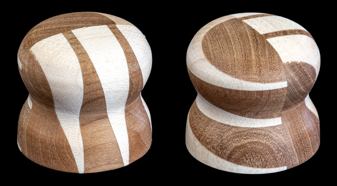
Once lacquered rare earth magnets are added to a recessed hole in the base and they are ready to use.  Below are the completed magnets.

I started this project wanting to do something a little more complex than the earlier segmented bowls I had done and this one certainly fit the bill.  When starting out I knew that getting all the angled pieces in the main feature layers to match identically was going to be a challenge and it was.  That said it was totally worth it.  As to making another bowl of similar complexity... ask me in a year or so.

Monday, May 22, 2023

Segmented Bowl – # 12 Gluing Halves, Final Shaping & Finish Selection

With the interior shaping and finish sanding 95% done the last bit of work to do before gluing the two halves together is to apply tape inside the bowl at the glue joint.  This is to keep any glue runs on the inside from adhering to the area adjacent to the glue joint. This makes cleanup and blending the inside joint a lot easier.

With that done the glue is applied to the top half’s joint, it’s set in place, the alignment of the two layers set and the two halves are clamped together using the tailstock to apply pressure.  Since another set of hands are needed my wife tightened the tailstock while I held the top half in place.  The little glue squeeze out on the outside gets cleaned off and the assembly is left for the glue to cure overnight.  The red arrow in the bottom photo points to the top/bottom joint.

The next day the tape gets removed from the inside which worked very well with only a little ridge of glue to be removed.  No photo of that since I can’t figure out a way to get the camera inside the bowl to take one.  What’s shown below is the bowl removed from the lathe and stood upright so the shape could be critiqued to see what refinements need to be done since that can’t really be done horizontally in the lathe.  To my eye there are four places that need some work.

  1. The shoulder’s radius is too small so I need to bring this point in to soften the transition between the top and the feature band.
  2. Here the top of the just completed joint is just slightly larger than the layer below.  This and the shoulder being oversize were planned to give me extra material to blend both together for a good flow up from the feature band.
  3. It’s almost impossible to see here but there is a slight swell at this point that breaks the smooth curve down to the base.  However, when running my fingertips across the surface it certainly can be felt.
  4. The base is too wide and needs refinement.  This too was planned because I wanted to keep it as wide a possible for stability while turning.  If it is too small then the piece is not rigid enough when turning and you can get vibration out at the end and that causes all kinds of problems.  This will be the last area addressed once all the others are done and the piece is sanded.

Here is the finished turned and sanded bowl except for the bottom ¾” or so.  That will be done later.  The bowl is now ready to be put back in the lathe and parted off the base.  This follows the same process as parting off the top done earlier.  Once cut off the base needs to be cleaned up but before that can be done an adapter has to be made to go between the base and the tailstock of the lathe.

The adapter starts with a cylinder just over 2” in diameter then has the right end turned down to 2” shown in the top photo.  This smaller end will fit in the recess under the oak plywood inset base that was put in early on.  The red arrows in the bottom photo from early on in the project shows the plywood and the recess it will go into.

The other end of the adapter gets a hole drilled in it which is then tapped adding threads (top photo) so it can be screwed onto the live center in the tail stock.  The bottom photo shows the threaded adapter and the threaded end of the live center where it will go.

Here the bowl is mounted back in the lathe with the adapter in place.  As the adapter is sized to just fit in the recess it holds and centers the bowl so I can clean up the last little bit of the bottom of the bowl.

The top of the bowl fits over the tenon on the faceplate/mounting block assembly and has a paper towel to take up slack and cushion the edge of the top since it has been finish sanded.

In the photos below the adapter is in place in the bottom of the bowl and you can see how it just fits in the recess.  The left photo is what the bottom looked like after it was cut off the mounting block while the right photo shows what it looks like after it’s cleaned up and sanded.  At this point the woodworking part of the bowl is done and I am ready for the finishing to begin.

However, before the finishing can begin cleanup needs to be done in the shop to reduce the amount of dust in the air since it seems like a wet finish attracts dust like a magnet.  The first place to start is at the lathe.  Now early on I did clean up around the lathe each day but got lazy and decided to wait until the turning was all done.  As you can see there are a couple of pretty good-sized piles of shavings plus one more behind the lathe that you can’t see.  All told just around the lathe there was enough to fill a couple of garbage bags.

Once the shop is cleaned up, the application of the finish can start.  In an earlier post I mentioned that I would use a Wipe-On polyurethane rather than my usual sprayed lacquer finish.  Spraying a lacquer finish on the outside of the bowl is easy as it’s no problem to get to all the outer surfaces.  That’s not so with the inside as there is no way I can get the spray gun inside the bowl and using a brush won’t work. 

That left me with a few wipe-on finishes like Danish Oil Finish, boiled linseed oil or a wiping varnish.  Of those I like Danish Oil Finish or a wiping varnish like Wipe-On polyurethane.  In general, I use Danish Oil Finish when the piece can have a rough life and will probably need the finish refreshed sometime in the future.  An example is tool handles or toys that kids will play with neither of which applies here.  I also want to have the option to control the amount of shine the final surface will have and with Danish Oil Finish it’s usually a matt finish.  All this led me to using Wipe-On polyurethane.

Next Up – Finishing & Wood Leftovers

Monday, May 15, 2023

Segmented Bowl – # 11 Refine Bowl’s Shape, Cutting Top Free & Finishing Top Lip

While adding the last few layers onto the top half stack and waiting for the glue to cure between layers I started to refine the bottom half of the bowl's layers exterior down to its near finished size.  This process starts by taking the finished diameter at the glue line between layers off a drawing and laying them out on the bowl.  The drawing below shows the finished inside and outside radius of all those points.

Below the top photo shows the drawing, bowl and the tools including my homemade large diameter calipers needed to mark both the current diameter and final desired diameter on each of the layers.  The bottom photo shows a closer view of the current dimension at the top and the desired finished dimension (underlined) at the bottom.

With the dimensions marked the bowl is mounted on the lathe and steps are cut just a little larger than the finished bowl diameter.  These will act as depth guides when turning.  The three layers on the left do not have the depth guide cut as I want to keep the maximum thickness there for stability when turning the layers farther out.  Those layers will get turned later once the outer layers are finished.

Here I am back working on the bowl’s top half.  At long last the 21st and final ring is glued and clamped in place to the top half.  I know someone is going to ask why is there only 16 layers listed in the above drawing rather than 21.  That’s because layers 8 and 10 are really made up of two thin layers that I chose to list as “a” and “b”.  Since they are so thin there is going to be very little difference in their finished diameter.  Also, layer 9 is made up of the 4 center feature rings and I will blend their final profile by eye as the turning progresses.

After the top’s last rings glue has cured, I took off all the clamps, mounted it on the lathe and removed all the steps between the layers to get a very rough shape.  Once roughed out the top half is set on the in-progress bottom half to get a general idea of what the bowl is going to look like. 

From that point on the work of refining the shape based the outside diameters alternates between the top and the bottom halves.  Once I get close to the desired dimensions the final shape is determined by setting the halves together and looking at the bowl to see where changes need to be made.  The left bowl is an intermediate step and the right represents the near final shape before they get glued together.  However, once the two halves are glued together there will be more refinement done particularly along either side of the final glue joint.

 Turning the inside of the top and bottom smooth and the wall to a constant thickness is next.  Also, the inside and outside diameters where the two halves meet need to be matched as close as possible.  The outside is more forgiving since once glued together the bowl can be mounted in the lathe and any irregularities blended together.  However, any misalignment on the inside is way harder to correct.  Here is the top finished and ready to be parted or cut off the lathe’s faceplate and mounting block.   

The first step in parting off the top is to drill a small hole (red arrow) through the waste in the top layer as in the top photo so I can see exactly how much of the wall remains holding the bowl on.  The bottom photo has been cut down so there is a band of just under 1/8” thick holding to bowl on and that’s as close as I want to get. 

To finish removing the bowl a Japanese pull saw is used.  The removed top half along with the saw is in the top photo and the bottom photo is a close view of the resulting rim.  The red arrows show the thickness of all that was holding the piece on.

To clean up the cut edge the piece needs to be mounted back on the lathe with the rough edge facing out.  That’s done using a jumbo set of jaws mounted to the scroll chuck shown in the top left photo.  In operation when the chuck is closed it pulls the eight rubber bumpers at the perimeter down to tightly to hold the piece in place shown in the bottom left photo.  The right photo shows the top edge cleaned up.  It’s not finished but is set up for use when the top and bottom pieces are glued together.

Doing a dry fit for the gluing is next which when done looks like the photo below.  However, before I could do that the wood mounting block that’s on the just cut off face plate needs to be modified and an adapter has to be made (red arrows).

First is to modify the wood mounting block that’s screwed to the just cut off face plate by turning the mounting block down some to make a tenon that will fit inside the bowl’s top opening.  During gluing the tenon will center the top half of the bowl and the flat face will provide the surface where the clamping force is applied. 

The second piece is an adapter that goes between the tailstock which is on the right side of the dry fit photo above and the modified mounting block/face plate.  One end of the adapter is sized to just fit inside the threaded neck part of the face plate that screws to the lathe headstock.  The other end needs to have a taper that will match up with the #2 Morse taper inside the tailstock.  Turning the left side of the adapter is easy but the taper on the right side is a bit more difficult since the taper angle needs to match the taper inside the tailstock.  After some measuring and a bit of fine-tuning fitting the piece fits snuggly in the tailstock with no wiggling.

Next Up – Gluing Halves, Final Shaping & Finish Selection

Monday, May 8, 2023

Segmented Bowl – # 10 Feature Ring Install, Secondary Feature Ring Build

Deciding which way to stack the layers that make up the main feature rings is next.  There are two different ways as shown in the two photos below.  For me my eye travels from right to left across the layers and having the hard vertical edge of the cherry on the right as in the bottom looks better.  I think it makes the layers look stair stepped versus a ramp like in the top photo.  Others may have differing opinions.

This bowl will have two individually turned halves.  The bottom section is up through the main feature rings and the top section is down to the top main feature ring.  Once shaped inside and out the two halves get glued together then the final detailing is done.  What that means is with most of the rings made and ready to glue to the bottom half I will start working on the top half.  The top starts by using a second face plate along with a mounting block just like the bottom half.  Here that’s been done along with the bowl's very top layer glued on turned round and the face squared to the lathe’s main axis.

Adding the second layer to the bottom half feature ring is next.  Normally the joints in the layers are staggered by half.  However, with the four feature layers they are staggered by thirds.  That requires marking the first layer as shown below.  When I glue on the second layer it goes on the right pencil line, the third on the next line to the left and the fourth layer lined up with the existing layer’s joint.

There are three regular layers at the top half before getting to the feature layer there so right now in progress are the main feature rings being glued and turned round on the bottom half.  At the same time the top half ring’s segments are being cut, glued into rings then flattened with the thickness sander and glued on.  This is what all that looks like.  At the far right is the bottom half with the second feature layer glued on.

While the three glued up pieces are curing it’s back to working on the top half’s feature layer.  The blank I made earlier is thicker than needed so I will use the bandsaw to bring it down close.  Here is the bandsaw setup from the outfeed side.

After bandsawing and running the piece through the thickness sander the blank gets squared up and ripped into four strips.  Each of these strips when cut give four segments.

Next is to start cutting the segments which is a multistep process that requires a fair amount of measuring plus some trial and error to get the exact sizes needed.  The top photo shows the first cut which is set using a stop block on the left.  Here the critical dimension is the distance between the right edge of the maple strip and the right cut edge.  Once that’s set the right end's stop block is set and a scrap used to check the size.  When it gets really close, I use a playing card to move the stop one-hundredth of an inch at a time as shown in the bottom photo.  The inset shows the end result being just .0005” over and that’s plenty good.

With that stop in place the first segment is flipped top to bottom and cut.  That’s followed by cutting the same end segment from each of the other three strips.

Cutting a segment from the other end is next.  It follows a similar process except the reference end up against the left stop is not square so an angled piece is used.  The top photo shows that setup and the waste cutoff.  Using the already set stop on the right the segment is cut to final length leaving only the center section to be cut.

Here is what the four strips look like with the end two segments cut to size leaving just the center four to be sized.


These last four follow the same process albeit with the left stop set at a different spot as shown in the top photo.  The bottom photo shows the piece flipped over and cut using the same right stop as the rest of the segments.  A side note; when I cut these small pieces I used the eraser end of a pencil to hold them in place and not my fingers.

Once the segments are cut, they follow the same assembly procedure as the other rings.  Here the ring has been glued to the top stack, turned round and the next layer glued on.  This last ring presented a little problem because the previous layer did not have a large enough “step” for the clamps to get good support.  The fix is to use some spacers (red arrows) the same thickness as the layer, in this case leftover cutoffs from the feature layer segments.  There are still four more rings to add to the stack, so a bit to go.

While I was working on above the top feature ring the four main feature rings got glued on and turned round.  This completes the stacking of rings on the bottom half and this is what that looks like.

Next is to knock off all the corners, get rid of the steps turning both the outside and inside down to a rough shape.  This makes it look a lot more like a bowl versus something made out of LEGO® blocks.  There is still a long way to go but this will give you an idea of how the turning progresses.

Earlier in this project in the seventh posting Assembling the Base Parts & Adding Layers I showed one way to help keep the new rings from sliding around by using some Quick-Release Ratcheting Hand Clamps.  They work OK but can slip a bit when the other clamps are tightened.  A more secure way is to use “F” clamps that have a much greater clamping force and are much more resistant to being pushed out of place.  The photo shows one in place.  The only thing to remember is to remove them after about 10 minutes.  That keeps them from being glued in place or in this case staining the oak if the glue reacts with the oak and steel of the clamp.

 Next Up – Refine Bowl’s Shape, Cutting Top Free & Finishing Top Lip