While adding the last few layers onto the top half stack
and waiting for the glue to cure between layers I started to refine the bottom
half of the bowl's layers exterior down to its near finished size. This process starts by taking the finished
diameter at the glue line between layers off a drawing and laying them out on
the bowl. The drawing below shows the
finished inside and outside radius of all those points.
Below the top photo shows the drawing, bowl and the tools
including my homemade large diameter calipers needed to mark both the current
diameter and final desired diameter on each of the layers. The bottom photo shows a closer view of the
current dimension at the top and the desired finished dimension (underlined) at
the bottom.
With the dimensions marked the bowl is mounted on the
lathe and steps are cut just a little larger than the finished bowl diameter. These will act as depth guides when turning. The
three layers on the left do not have the depth guide cut as I want to keep the
maximum thickness there for stability when turning the layers farther out. Those layers will get turned later once the
outer layers are finished.
Here I am back working on the bowl’s top half. At long last the 21st and final ring is glued
and clamped in place to the top half. I
know someone is going to ask why is there only 16 layers listed in the above
drawing rather than 21. That’s because
layers 8 and 10 are really made up of two thin layers that I chose to list as
“a” and “b”. Since they are so thin there is going to be very little difference
in their finished diameter. Also, layer
9 is made up of the 4 center feature rings and I will blend their final profile
by eye as the turning progresses.
After the top’s last rings glue has cured, I took off all
the clamps, mounted it on the lathe and removed all the steps between the
layers to get a very rough shape. Once
roughed out the top half is set on the in-progress bottom half to get a general
idea of what the bowl is going to look like. 
From that point on the work of refining the shape based
the outside diameters alternates between the top and the bottom halves. Once I get close to the desired dimensions
the final shape is determined by setting the halves together and looking at the
bowl to see where changes need to be made.
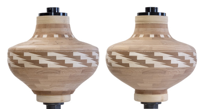
The left bowl is an intermediate step and the right represents the near final shape before they get glued together.
However, once the two halves are glued together there will be more
refinement done particularly along either side of the final glue joint.

The first step in parting off the top is to drill a small
hole (red arrow) through the waste in the top layer as in the top photo so I can see
exactly how much of the wall remains holding the bowl on. The bottom photo has been cut down so there
is a band of just under 1/8” thick holding to bowl on and that’s as close as I
want to get. 
To finish removing the bowl a Japanese pull saw is
used. The removed top half along with
the saw is in the top photo and the bottom photo is a close view of the
resulting rim. The red arrows show the
thickness of all that was holding the piece on.
To clean up the cut edge the piece needs to be mounted
back on the lathe with the rough edge facing out. That’s done using a jumbo set of jaws mounted
to the scroll chuck shown in the top left photo. In operation when the chuck is closed it
pulls the eight rubber bumpers at the perimeter down to tightly to hold the
piece in place shown in the bottom left photo.
The right photo shows the top edge cleaned up. It’s not finished but is set up for use when
the top and bottom pieces are glued together.
Doing a dry fit for the gluing is next which when done
looks like the photo below. However,
before I could do that the wood mounting block that’s on the just cut off face
plate needs to be modified and an adapter has to be made (red arrows).
First is to modify the wood mounting block that’s screwed
to the just cut off face plate by turning the mounting block down some to make
a tenon that will fit inside the bowl’s top opening. During gluing the tenon will center the top
half of the bowl and the flat face will provide the surface where the clamping
force is applied. 
The second piece is an adapter that goes between the
tailstock which is on the right side of the dry fit photo above and the
modified mounting block/face plate. One
end of the adapter is sized to just fit inside the threaded neck part of the
face plate that screws to the lathe headstock.
The other end needs to have a taper that will match up with the #2 Morse
taper inside the tailstock. Turning the
left side of the adapter is easy but the taper on the right side is a bit more
difficult since the taper angle needs to match the taper inside the
tailstock. After some measuring and a
bit of fine-tuning fitting the piece fits snuggly in the tailstock with no
wiggling.
Next Up – Gluing Halves, Final Shaping & Finish Selection

No comments:
Post a Comment