
Some years ago (2018) I replaced a tattered split wooden
handle on a small stainless-steel spatula with a new Mesquite handle. The top photo below shows the spatula with the
old handle which my wife got in 1977 and at the bottom the completed mesquite
handle replacement. I did make the new handle a little larger and softened the edges more than in the original to fit my wife's hands.
At that time, we also had a second similar spatula gotten
at the same time whose handle did not really need replacement. However, in the intervening four years that
spatula’s handle degraded to a point where it also needs to be replaced or
fitted with a new handle. Here is what
that spatula looks like now.
I could have used another piece of mesquite to make the
handle but wanted to try something different.
While looking for a handle replacement I came across a material called
Micarta® used to make “scales” or handles for knives. The one I selected is a thermoset laminate
made from layers of green dyed linen and phenolic consolidated under heat and
pressure. The left two photos below
show what the phenolic (top) and linen (bottom) layer looks like while the right
photo shows the layeres on edge view.
The first step is to remove the rivets holding the handle
in place. That starts by using a
spring-loaded punch to dimple the center (top photo) of the rivets in
preparation for drilling them out. The
bottom photo shows the drilling in progress and a closer view of the punch mark
on the left rivet.
This photo shows the rivets drilled out and the handle
removed. The red arrow points to one of the
removed rivets. As you can see, I did not
have to drill it out completely but just deep enough to get through the flared
out top section. Once they get removed
you can see where the wood around the rivets had decayed and chipped out.
Starting work on the scales is next. There are two pieces of Micarta® in a package
but because the completed handle is fairly narrow, I can take one of the scales
and cut it in half. However, first is to
put a finished, polished rounded edge on one end of the blank. This is the end that will taper down to make
a smooth transition to the blade of the spatula. The shaping and finishing process is not
covered here but will be later. With
that done a strip of masking tape gets put on the blank and a knife edge
marking gauge is used to cut a line down the center of the blank. The left photo shows the marking gauge and
the line. The right photo is a closer
view of the business end of the gauge.
The knife edge is a reground X-Acto blade. Side note the marking gauge is one I made out
of lacewood.
The bandsaw is used to cut the blank apart. It works well and since it has a thin kerf
not much material gets removed when making the cut.
While the bandsaw makes a narrow cut and a decent
surface, they do need some clean up before moving on. This gets done using the big disk
sander. The surface is by no means
finished but it’s what’s needed at this point.
After the edges are cleaned up a thin offset gets routed
the same thickness as the blade. This
offset is only 21 thousandths of an inch thick.
This is so there won’t be a gap due to the blade’s
thickness when the handles get attached.
The top photo shows the router setup.
The piece of plywood with the handle keeps the blank square with the
fence and my fingers away from the router bit.
The middle photo is a closer look and the bottom photo is of the
finished routed offset.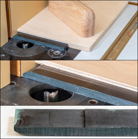
The handles can be attached either mechanically as in
riveted like the original handles or attached with an adhesive. I decided to use a long cure epoxy because I
like the no hardware look and the finished piece won’t be under much
stress. If I were making a big machete
used for chopping or something that was under a lot of stress or shock load
then I would use a mechanical fastener along with the epoxy. The top photo shows the initial setup I used
to align the handle with the blade.
Because the handle is slightly thinner than the blade two playing cards
set under the handle raises it up so it’s centered and in-line with the
blade. In the bottom photo the epoxy has
been applied and the handle halves clamped in place. This will be left alone for a full 24 hours
to cure.
In the top photo the clamps are removed and the handle is
ready for shaping. There are a few
places where the epoxy needs to be cleaned up but it’s good and solid. Next is to flush the two sides and round the handle’s end using the big disk sander.
From there the drum sander is used so the center section of the handle
gets slightly narrowed to form a waist.
After that a 1/8” radius bit is put in the router and the edges are very
carefully routed. Being careful is
important since it would a bad thing if the spinning bit contacted the
blade. From there it’s back to the drum
sander to touch up the sides which is what the bottom photo shows. The light white line across the handle is a
reference mark for the start of the waist's curved edge.
Final shaping is done by hand sanding the edges until the
handle feels good when held. Only a
couple changes in profile were required.
First, the curved transition from the side to the top got softened so
the transition to the top flat is more gradual.
Second, in the waist area the overall size of the arc was made larger
and the transition to the flat top is more gradual. In both cases the side to top transition more
resembles an ellipse versus the initial circular arc cut with the router. It’s all a matter of what feels
comfortable. The photo shows the
clamping setup and the first set of dry sandpaper grits starting with a coarse
120 grit and ending with a fine 600 grit.
The bottom photo shows the handle with all that done.
Next is to wet sand working through finer grits until
ending at 1500 grit. When that’s done
the surface looks like the top photo.
Most of the scratches are gone but the surface does not have as high a
polish as I want. The final polishing is
done on the lathe using a flannel/cotton mix buff loaded with white diamond
abrasive. 
The end result is shown in the photo along with the
four-year-old mesquite handled spatula with its lacquer finish that’s been in
continuous use. My guess is the new set
of Micarta® handles will do at least as well.
I mentioned the profile of the handles depend on what feels good to the
user. As you can see the two spatulas
handles are slightly different in shape.
The mesquite was shaped to be comfortable in my wife’s hands and the
Micarta® one in mine. Neither is
uncomfortable to use it’s just that one feels a little better than the other
depending on the user.
I would be the first to admit that doing the handle replacement would not stand up to a financial cost/benefit analysis since the cost of the Micarta® scales is probably half the cost of a new spatula. That said there is a case to be made for reuse and repair of things versus just throwing them away and buying new. An equally good or better reason is woodworking is a hobby and I derive a lot of satisfaction from the work. In the final analysis I suppose that's a good enough reason.


