Router Plane

Monday, December 28, 2020

Danish Cord Seat - #4 Assembly, Finishing & Seat Weave Layout

Assembly and glue-up is next.  Here are all the parts and pieces set up and ready to go along with the clamps that will be used.

This is a little closer view.  I am using a Type III waterproof glue not because I need the joint to be waterproof but because the working time with it is a little longer than the regular glue and I think that I will need every bit of it.  The folded playing cards will be used as my “brush” to spread the glue.  As a preventative aid to make sure all the pieces go in the right places facing the right directions the tenons as well as the mortises are all labeled.  Since the tenons are not centered accidently reversing or flipping one would fit but would make for a real problem.

After a frantic 10 minutes here is the seat all glued together.  Everything came together straight and square with all four legs sitting flat on the bench.

To help lock the tenon in the mortise I used a pneumatic pin nailer to add a one inch long nail from the inside face of the leg through the tenon then continuing on into the far side of the leg.  They are very thin and almost disappear.  I think that when the piece is finished, they will be invisible but then to find them you will have to turn the seat upside down.

Applying the India Ink is next and it’s fairly easy to do.  A piece old cotton t-shirt about 2” square is dipped in the jar then rubbed into the oak making sure the pores get covered.  Here is what it looks like with the stretchers having one coat applied.

After the first pass dried there were a fair number of undyed little specks in the bottom of the pores that needed touching up.   That was done using a small artist’s brush and stippling the surface to get the ink all the way into the bottom of the pores.  When all done this is what it looks like ready for the lacquer to be sprayed on.  One other thing, to keep the legs on the painter’s triangles and not slip off I drilled a small hole in the bottom of the legs for the point to set in.

This is after I had finished the third and last coat of lacquer.  You can see the air-brush in the lower right.  It’s my usual setup with satin lacquer thinned by about a third or so.   The seat frame is set on painter’s triangles to raise the seat up to provide a clean spray at the bottom of the legs.  They are set on a sacrificial piece of carboard set on plywood temporarily covered with paper.  All that is set on a rotating table so I can spin the piece and easily get to all sides.  One note, after the first coat of lacquer was wet sanded with 2,400 grit to remove dust nibs I had to go back and touch up the black in a few places where the oak shown through. 

When getting ready to do the third coat I notice the spray pattern was not right.  Upon inspection some of the tiny holes in the nozzle had become partially clogged distorting the spray pattern.  The solution is easy just soak the nozzle in lacquer thinner and blow them out with compressed air.  I had a small measuring cup used to measure small amounts of denatured alcohol when mixing dye about the right size like the one on the right in the picture below.  I filled it with lacquer thinner dropped the nozzle in put a cover over it to reduce evaporation and went to work on other things.  When I came back about 15 minutes later the thinner had dissolved the cup and the thinner had run out all over the piece of cardboard.  What remained of that cup is shown to the left of the other one.  Needless to say, I was a little surprised.  After cleaning up the mess the nozzle was soaked in thinner in a glass jar this time.  Once cleaned out the air brush worked great and the third coat of finish applied.

With the seat frame completed I can start on weaving the seat.  That begins with  laying out the location of the warps.  Warps are the framework of the seat and are put on first here running from front to back analogous to the sides of a loom.  Once they are all on the weaving of the wefts can begin.  An odd number of warps are laid out on the front and back stretchers.  I used a digital caliper’s points to mark the spacing followed by a marking knife and square to get scribed lines.  In the photo below the faint right two lines have been cut in with the marking knife while the two pronounced ones on the left have had some chalk rubbed in to make them easy to see.

The Danish cord I am using is made outside of Copenhagen and is the same 3 ply cord found on Scandinavian chairs made from the 1950's on.  The individual plies of the laced cord are twisted to give a rope like finish.  It is also available in a smooth finish but I like the way the twisted cord looks. This is a 2-pound bundle.  It does not show up in the photo but to keep the ends from fraying I dabbed some glue on them.  When cutting off usable lengths I will do the same on the newly cut ends.

Next Up – Mounting the Warps

Monday, December 21, 2020

Danish Cord Seat - #3 Cutting Tenons & Routing

With all the mortises made it’s time to work on cutting the tenons that go in them.  The first pieces will be the front and back stretchers shown in the photo below.

Since the pieces were a little long, they are cut to length in the chop saw using a stop block.  That’s followed by laying out the tenon.  Because this tenon is not centered side to side along with the regular layout marks I have added the depth of cut for each face.  Below the top piece has had the first face cut making two passes using the stacked dado. 

My stacked dado set has two 1/8” outer blades, four 1/8” chippers, one 3/32” chipper one 1/16” chipper and 10 shims ranging from .004” to .02” thick.  Using them in combination I can cut dados ranging in width from ¼” on up.  This setup uses two 1/8” outer blades and two 1/8” chippers which gives a ½” total cut width per pass.  I could have added more chippers to get to the exact width but then I would have had to add a sacrificial piece to the rip fence so I wouldn’t cut the fence itself.  It’s just easier to stack pieces up a bit over half the total and make two passes.  Additionally, a narrower cut puts less strain on the saw and decreases the total rotating mass which reduces the time it takes the blade stack to spin down and stop.  Here is what the selected parts look like.

For this tenon the second and third cuts will both be ¼” deep so the dado set will be raised and the cuts made.  With these cuts the three sides of the tenon will be done with just the thickness to do.  The last cut establishes the thickness of the tenon which is the most critical and that’s because it needs to be a snug fit.  Too tight and it could cause the leg to split, too loose and the glue joint will be weak.  The height of the tenon is not as critical so it gets cut first allowing me to test the width to get it just right.  Here is what the finished tenon looks like.

Cutting the double front to back stretchers is next. 

The layout follows the same process as before with one addition.  The top and bottom stretchers are the same size but have a different orientation.  By that I mean the top stretcher is wider than tall and the bottom stretcher is taller than it is wide.  Because they are both 7/8” by 1” it makes it really, really easy to get them mixed up and make an incorrect cut.  To help keep that from happening a 1 through 4 numbered cut sequence is added.   I also have a couple of cutoffs for test pieces.  The actual cutting follows the same procedure as the front/back stretchers.  I just need to be extra careful making the cuts.

Here is what the two sets of stretchers look like when done set in the orientation they will be installed.

Now with all the tenons cut I can do a test fit.  In doing so I found that about half of them were just a hair too tight.  That’s solved by taking a couple of passes on the tenon face using a piece of 120 grit sandpaper attached to a flat surface.  Here is what the friction fit assembled seat looks like.

Routing a radius on all but one of the exposed edges is next.  There are two and maybe three different sized radius router bits to be used.  First is a 1/8” shown below being used at the bottom of the legs.  The piece of plywood behind the leg with the handle is a backer board whose purpose is twofold.  First, is to keep the leg square with the fence and second to act as a backup to reduce chipping when the bit exits the end grain cut.  This bit also gets used on one edge of the legs and the tops of the six horizontal stretchers.  Because it is so small the radius can be cut in a single pass.

Next is a 3/8” radius for the top of the leg and most of its remaining edges plus the bottom edges of the stretchers.  The setup is similar to the previous 1/8” bit except that instead of being cut in a single pass I will make three passes.  That’s done to reduce the load on the router and reduce chipout.  While going from a 1/8” bit to a 3/8” bit doesn’t sound like all that much.  However, when you do the math the total cross-sectional area removed is 9 times as much.  Here is what that looks like ready to make the last pass on the edge of the legs.

With all the routing done the flat faces and most of the edge routing can be sanded using a ¼ sheet pad sander.  However, there is still some hand work to do on the top and bottom of the legs.  Here is a before and after of the top of the leg corner blending where all of the edges were routed with the 3/8” bit.

The other two top leg corners are a little different in that one vertical edge has a 1/8” roundover and the one facing the camera has a hard 90-degree edge.  The top photo is before the blending and the bottom one after.

The bottom of the legs also need help in blending all the routed edged together.  The left leg is the before and the right is the after.

Most of the blending is done with the fine end (right) of this half-round 4-in-Hand rasp.  The final blending is done by hand using 220 grit sandpaper until it flows and feels smooth with no hard edges.

The stretchers are treated a little different in that they are not sanded at all.  The flat faces are left with the 80-grit surface right out of the thickness sander plus the routed radiuses are not sanded either.  The reason for this is when the seat cording is wrapped around them it needs the wood surface to have some tooth to in order grab onto.  With that in mind here is an end view of the stretchers.

Next Up – Assembly & Finishing & Seat Weave Layout

Monday, December 14, 2020

Danish Cord Seat - #2 Shaping & Mortising the Legs

First parts to be made are the legs.  I started on them because they have quite a few mortises and it is my procedure to make the mortises first then fit the tenons that go in them second.  I do it in that order because the mortises are made on the mortising machine which uses a fixed width chisel/bit combination.  The tenons on the other hand are cut on the table saw making their finished size adjustable.  Anyway, it all begins by printing out a full-size pattern of the upper part of the leg and gluing it to a piece of ¼” plywood.  That’s shown below along with the leg blank.

The straight part of the pattern is cut on the table saw while the curved part is cut with the jig saw using a ground fine tooth blade.  The table saw cut is right at the finished width while the jig sawn part is cut slightly wide of the line to allow for a smooth curve and transition into the straight part.  Here the straight cut is done and a little bit of the curved cut has been made with the jig saw.


Next using the oscillating drum sander, the jig sawn cut is smoothed and blended into the straight table saw cut.  I start with a coarse sanding sleeve then use a fine grit sleeve.  That’s followed by some hand sanding to completely blend things together.

Layout of the curve on the legs along with all the mortises is next.  The legs are not all the same, there are mirrored pairs.  Here you can see how the they will be arranged.  Note the labels, LF for Left Front, RF for Right Front and so on as to which one goes where.

Cutting the straight part of the legs comes next and that’s done on the table saw with a stop to keep me from cutting too far along the line and getting into the curved area.  While it looks like the cut could be continued that’s deceiving since the bottom of the blade cuts farther than the exposed part.  The blue tape is there to give me a good place to grab when pulling the leg back out.

After the straight cut it’s over to the bandsaw to rough out the curve.

Fairing the bandsawn curved edge and the table saw cut straight section together is next.  That’s done using the same process as when the template was made.  The top photo has the finished blended edge completed on top with the bottom showing what it looks like right off the bandsaw.  The bottom photo is a closer look.

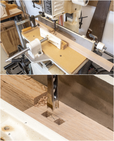
Cutting the mortises in the leg is next.  I use a dedicated mortise machine to make them.  It uses mortising bits comprised of a square hollow chisel that squares the edges and a special drill bit that leads the hollow chisel cut and removes wood shavings all mounted in a powered head.  A long handle gives the mechanical advantage for plunging the cut.  In use the piece to have the mortise drilled is clamped to a table that moves front to back and side to side.  The side to side movement can be limited with stops for making identical repeating cuts.  Depth of cut is controlled with a stop on the head.  When my son was young, I bet him that I could drill square holes.  He didn’t believe me and thought it was impossible.  When I took him into the shop and made a couple the look on his face was priceless.

Here is what the setup looks like with the ends done.  They are cut first so there is even lateral pressure on all sides of the bit.  If one side is open the bit could drift throwing the mortise out of square.

This is what the finished mortise looks like.

Since the legs are mirrored pairs two different setups are required.  This is what the second setup looks like.  All the measurements and process are the same just reversed. 

For the next set of mortises the layout starts on a test piece using a dial caliper and marking knife.  Because a knife mark is hard for me to clearly see on light wood like oak chalk is rubbed into the cuts making them readily visible.  In the bottom photo the right mortise is easy to see while the one on the left is not so visible.

To make sure the chisel is aligned with the layout lines the end of a small steel square is set against the chisel/bit set and the table moved in or out until they are aligned.  The side to side adjustment follows the same process except that when aligned at the ends the stops are locked in place.  Once set up you can easily make two or fifty identical pieces.

Once a test piece is cut and all the measurements check out there is one last step before cutting the second set of mortises.  A filler plug is needed where two of the mortises will intersect.   The plug is made out of scrap oak sized so it fits snugly in the mortise.  The reason the plug is needed is to prevent a blowout in the first mortise when the second one is cut and punches through the side of the first one.  The top drawing shows the intersection highlighted in red and the bottom photo shows the filler plug in place. 

With the plug is in place the remaining mortises can be cut being sure to remember to make mirrored pairs.  After these mortises are cut the plugs can be removed and discarded.  Here are what the four legs look like with all the mortises cut.

Next Up – Cutting Tenons & Routing

Monday, December 7, 2020

Danish Cord Seat - #1 The Beginning

While looking through the October 2020 issue of Fine Woodworking I came across a fairly long and involved article on how to weave a chair seat using twisted Danish Cord.  It’s something I had never done and the process looked interesting.  It’s not that we really need any more chairs but I thought that I could make a case for a short seat in the bedroom to set on while putting my socks and sandals on.  I know it’s a pretty thin excuse to justify the project but it won’t take up too much space and I have all the materials on hand except for the Danish Cord itself.  That’s my reasoning (excuse) and I’m sticking to it. 😊  Below is what the finished project in the Fine Woodworking article looked like.

Now the article only covered the seat weaving and did not address building the wood frame for the seat which is fine with me.  I started by setting on a variety of chairs and benches around the house taking various measurements for a comfortable height, width and depth needed when putting my socks on.  The rough finish dimensions are for a seat about 16 ½” tall, 18” wide and 13” deep.  Now the actual seat area is smaller since it’s going to be inside the legs and stretchers.  Here is my conceptual drawing of the frame.  The tops of the legs are shown square but I will be rounding them over.

Almost all of my projects have a clear finish or maybe a little stain on oak.  Pieces made out of cherry, walnut, mahogany and the like are never stained.  However, in this case I thought about trying something different.  From what I can see the Danish Cord and finished unstained oak will be about the same color.  Since the seat weave is what I want to showcase some contrast is desired.   I suppose if the oak frame were painted a bright screaming pink or fluorescent green that would provide contrast but not in a good way.  

On a few projects I have ebonized wood by either dyeing or using a chemical reaction with the tannins found in oak and cherry.  Neither method has completely satisfied me so in doing some research I came across another method using alcohol colorfast black India ink and decided to try it out on red oak.  The selection of the oak works since it’s a nice strong hardwood and because the pores are pretty pronounced, I hoped that would provide some texture to the surface.   

When ebonizing cherry, it ends up looking like featureless lump of wood.  The same is true of the few pieces of Ebony that I have used although when finished they look almost like plastic.  That’s OK when used as a plug where the black color provides the accent but it’s not what I wanted here.  Below is one of the sample oak pieces I used along with the India ink and a piece of t-shirt to be used for application.

The application of the ink went pretty well except I did have to rub it into the surface to make sure all the pores got covered.  The first pass ended up with a good number of undyed little specks at the bottom of the pores.  As you can see the oak pores are still quite visible.

Next is to spray on a couple of coats of satin lacquer which seals the surface and gives a slight sheen to the surface.  I am really happy with the result and plan on using it on the project.

With the finish and material decided on going through the stack of oak looking for 1 ½” thick pieces for the legs and 1” thick pieces for the stretchers is next.  Here is the stack of stock to be used.  You may not be able to clearly see the writing on the pieces but they are all marked out with chalk as to what comes out of each board.

When I checked the raw stock to see if they were straight, flat and true they were close but not there.  Fortunately, none of them had any twist which is a pain to correct and most are close to being flat but all do not have a straight edge.  Here after the raw stock has been cut into rough lengths you can see the gap between the boards edge and my level.  This is typical of what needs to be straightened.

To straighten the curve out an 8’ level is clamped to the rip fence on the table saw then the piece is set against it so the center high point is facing the blade.  The fence is then adjusted to just skim the initial point of contact so when the cut is made is the convex curve is removed.  The board is then flipped over so the straight edge is against the level, the fence adjusted so when cut that edge of the board gets its concave curved edge straightened.  The long level has to be used so the heels of the piece are always against a straight edge during the cut.  If they aren’t then the cut won’t be straight.

After the two passes through the table saw the piece has straight parallel edges.  When set back on the level no light is visible between it and the piece confirming a straight edge. 

From here the pieces can be cut to their rough length and run through the thickness sander to flatten.  The same logic is used for this face as with the edges.  The high face goes through facing up until the entire face has been sanded then the piece is flipped over and the other side flattened. Side note, this only works with pieces thick enough to resist the flattening pressure of the rollers.

Once flat, straight and square the pieces are labeled as to what they will be used for and the edges marked showing which ones get trimmed to make the final blanks.

Here are the blanks all trimmed to their final width and thickness.  Cutting to length will come later.

Next Up – Shaping & Mortising the Legs