Router Plane

Monday, November 29, 2021

Greene & Greene End Table - #28 Final Assembly

This is the last post for this project.  Between coats of lacquer on the shelf I can take care of the few remaining bits of work on this project.  First is to assemble the drawer then reinstall the full extension metal guides and do any minor adjustment so the drawer is centered in the opening.

With the drawer in place the false front can be added 
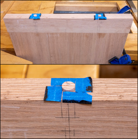
which starts by locating and clamping the handle to the false drawer front.  Once that’s done pilot holes the size of the screws root diameter get drilled through the front & into handle.  The blue tape on the drill bit is my depth gauge.

Next using spacers, the false drawer front is centered in the opening and clamped in place.  With that done using the already drilled pilot holes as guides the holes in the actual drawer can be drilled.  Here the false drawer front is centered with spacers ready to be clamped and drilled.

Enlarging the holes in the false front so the screw threads do not bite into it is next.  I want the screw threads to engage only with the handle so it pulls all the pieces tight together.  The holes in the drawer also get enlarged.  However, they get drilled out larger still to provide room for adjustment to the position of the drawer a little.  In the photo below the handle which is at the top has its pilot holes drilled, below that is the false front with the pilot holes enlarged for clearance.  On the bottom is the drawer itself whose pilot holes were enlarged to allow for adjustment.  Side note, on the extra holes in the handle.  They were for the screws that temporarily attached blocks to the handle when it was being sprayed with lacquer. 

Once assembled the false front gets centered in the opening and the attachment screws tightened.  Lastly, one additional shorter screw through the drawer into only the drawer front gets added in the center.

I left the top with all its coats of lacquer for wet sanding until the shelf was done too.  
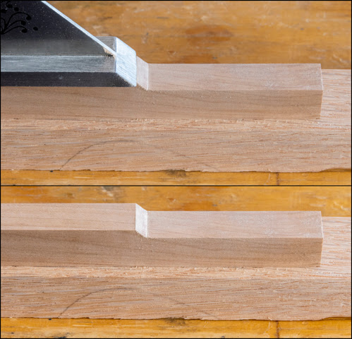
Both are wet sanded using the 8,000-grit pad.  That takes care of any dust that might have settled on the finish before it dried dust-free.   The top photo shows the top’s wet sanding in progress.  On the far left just barely in frame is the spray water bottle used to mist the surface.  The sanding pad has the loop part on its back while the circular block using has the hook half of the fastener on it.  In the close-up you can see the misted water droplets.

Once wet sanded the shelf gets installed first.  As it had already been fitted with the mounting holes drilled in the shelf and the screws run in all installing required was setting in place and putting the screws back in.  Here is what the installed shelf looks like from the underside.

Adding the top is the last bit of work.  That started by laying the top face down and centering the base upside down on it.  Once centered the screw locations are marked in the top using a screw large enough to fill the holes and slots width so the screw is centered.  After that the base is taken off, pilot holes drilled and the screws run in 5/8” because when permentaly installed that’s as far as they go into the top.  They are removed, the base set back on the top and the screws reinstalled.  It is a really tight squeeze getting the screws in and tightened.  The top drawing below has the piece inverted with the top down.  The bottom drawing is from a different angle with the spindle and one of the rails removed so the inside is visible.  As you can see it’s a pretty tight squeeze, there is only about 1 ½” side to side room.  Additionally, you can’t get a straight shot with the screwdriver into the screws since the side rail overhangs the side rail the screws run through.

The last bit of assembly is to put the drawer in which almost completes the project.  It does need to set in the shop for a couple of weeks so the lacquer completely gasses off until there is no longer any odor from it.  Below are a couple of views of the completed piece.  Because this will be used as an end table in the living room next to my chair the top will get some abuse from things being piled up, drinks spilled and who knows what else.  To provide protection a ¼” thick piece of plate glass will be added.


Monday, November 22, 2021

Greene & Greene End Table - #27 Installing Pegs & Fitting Shelf

The first pegs to be installed are the top ones on the tapered side of the legs.  Here is the installation setup.  It starts with a couple of old dish cloths acting as a pad between the bar clamp and the lacquered surface.  On the far left at the red arrow between the clamp and the leg is a tapered spacer held in place with the blue clamp.  The spacer matches the leg’s taper so the clamp has a flat surface parallel with the right-side clamp face.   On the right is the adjustable part of the clamp and the spacer with the hole that goes over the peg to set its protrusion.  

Below are closer views of the left and right sides of the clamping setup.  The top photo just shows the tapered spacer up a little closer.  The bottom photo shows the peg with the glue already applied in the mortise ready for the clamp to be tightened so the peg (black arrow) gets gradually pressed into the mortise to its correct depth.

It would be nice to say that tightening the clamp smoothly pressed the peg until the clamp head was tight against the spacer but that’s not what happened.  Tightening the clamp up did smoothly press the peg in to a point then it stopped and would not go in the rest of the way.  Not a good position to be in as I have a limited time to figure out what’s gone wrong before the glue sets and the plug is permentaly in there.  After some quick measuring it didn’t take long to find the problem.   All of the pegs for the upper two rails are made to fit the bottom rail mortise.  In doing so I had forgotten to take into account the leg taper which made the top mortise a little shallower than the bottom mortise.  Now it’s a race against time to remove the peg without damaging the edges of the mortise before the glue sets.  The removal consisted of drilling out the center of the peg with progressive larger bits until I got close to the edge of the peg but left the mortise untouched.  Then using a large thick bladed screwdriver and a mallet (I know wrong tool for the job) I could break away the remnants of the peg into the just drilled hole and remove them with a pair of needle nose pliers.  No photos of the process as I was too busy removing the peg to take any.

Fortunately, the edges of the mortise were not damaged and all of the peg came out.  The fix is simple just shorten the pegs by about 1/16”.  After marking what needed to be removed, I put the peg in a wood handscrew clamp and using the 12” disk sander took the excess off.  As some extra plugs were made running short was not a problem.

Using the correct length of plug this time everything went smooth with the clamp head pulling up tight to the spacer as shown in the top photo.  The bottom photo shows the plug glued in place with the correct amount protruding.  Also, because I want the plugs to look like through mortises all of them are arranged with the end grain the same direction.

The pegs in the front/back and at the sides are mirror images of each other.  This means when installing the opposite side peg the first one requires a spacer so when the clamp is tightened down the pressure just gets applied to the current peg and not the previously installed one.  What I don’t want to happen is to have the first plug pushed further into the mortise.  Here is the spacer used for the spindle pegs.  It’s just a little thicker than the amount the peg sets proud of the spindle’s face.

Once I got going installing the pegs was not hard but it did take a little time since there are 40 of them to put in.  Below is a back and side view once all the pegs were installed.

The front and right view is identical except the drawer is missing since at this point it still has to be assembled and installed.

Fitting the shelf comes next so I can get it stained and finished.   First is to install the shelf supports in the notches in the lower rails.  This photo shows the ebonized support, the notch it goes in and the screw that comes from below through the lower rail to hold it in place.  Note the FR (Front Right) on the support is so I know which support goes where.

Next is to cut a shallow dado in the bottom of the shelf to lock it into the support.  The support is 5/8” wide but to allow for the finish thickness and add a little play the dado is going to be cut slightly wider than the support.  The dado set I have includes various sizes of shims to fine tune the width of cut.  In this case a .004” shim gets added to the stack making the dado cut 5/8” plus .004”. 

This is the first cut dado; the blue tape helps reduce chipout when the blade exits the back side of the shelf.

With the right-side dado cut the shelf is set on the support as shown in the top photo.  The left dado gets marked using a marking knife to scribe a line on the underside of the shelf.  In the bottom photo you can see the scribed line just to the right of the marking knife’s tip.  When I line the outside edge of the dado blade’s tooth right on this line the resulting dado should line up exactly with the left support.

With the shelf fitted the mounting screws get run up through the center hole and edge slots in the support into the shelf.  The slots are there to allow for the expansion and contraction of the shelf.  From there it’s a simple matter of doing the finish sanding, breaking the sharp edges and staining all the shelf’s sides.  Here that’s done along with the underside sprayed with 1 coat of lacquer.  The rest of the finishing process is done the same as the top so I won’t go though it again.

Next Up – Final Assembly

Monday, November 15, 2021

Greene & Greene End Table - #26 Finishing & Installing Pegs Part 1

As mentioned before the finish is lacquer or really a nitrocellulose satin lacquer.  It is the finish I use on most of my projects and is applied using the airbrush or a HVLP (High Volume Low Pressure) commercial spray gun.  This type of lacquer has to be sprayed, a brushed or wipe-on method is not an option.  Here is my typical set-up for mixing.  The can on the left is the lacquer, next to it is the thinner.  The two plastic bottles in front of the can of thinner have thinner in them.  Smaller intermediate containers are easier to use when measuring versus trying to pour without spilling directly from the gallon can.  To the right of the thinner is the flow enhancer.  Flow enhancer reduces bubbling and blushing caused by the effects of high heat and humidity during application by slowing the formation of a “skin” keeping the top layer of film open longer.  In front of it are mixed bottles of finish ready to be used.  Here in the desert the mix I use is 2 parts lacquer to one part thinner and a capful of flow enhancer per 24 ounces of mix.  Last the circular gray disk in the center front is the 8,000 grit abrasive pad I will use for final wet sanding/polishing once the final coat of finish has cured.

The HVLP system consists of a three-stage fan turbine that puts out only about 6 pounds of air pressure but a whole lot of volume and a spray gun.  The turbine is in contrast to the tank type compressor I use for the air brush.  It can easily generate 100 pounds of pressure per square inch but at a much lower volume.  The airbrush needs very little volume and a regulator/filter limits the pressure to about 20 pounds.  The photo below shows the turbine, hose and sprayer.  For comparison setting on the turbine is the airbrush and its hose which goes to the tank type air compressor.  The HVLP needs a much large hose due to the volume of air needed.

Here is the setup for spraying the base which is mostly done with the airbrush.  It sets on some painter’s triangles to hold the piece up off the carboard covered MDF.  To help keep the base in place I drilled small holes in the bottom the legs that the triangle points set in.  The carboard below is sacrificial so when it gets overloaded with lacquer overspray it can be replaced.  Under the MDF is a 12” diameter lazy-susan.  It allows me to stand in one spot and rotate the base to easily spray all sides. 

The top and drawer bottom are set on more of the painter’s triangles and sprayed with the HVLP system.  Here is the underside of the top with two coats of lacquer applied.  It needs to be wet sanded to remove any dust nibs prior to spraying on the final coat.  I do it first and the top’s exposed face last just in case the first sprayed surface gets dinged while setting on the painter’s triangles while the second surface gets sprayed.  

After the second coat all the airbrush sprayed surfaces get a light sanding with 320 grit paper and the HVLP sprayed ones get wet sanded with an 1,800-grit pad.  The finer pad can be used on the HVLP sprayed areas since the finish is smoother.  It’s not because the HVLP does a better job but because they are large flat pieces like the top or drawer parts that can be sprayed out in the open one at a time.  By contrast the base has all sorts of intersecting parts including some pieces that are close together.  It’s a real challenge to get the inside and outside sprayed working around all the obstructions.  With the early coats while I work my way around the base as one part is being sprayed the overspray lands on pieces beyond them creating a slightly rough surface.  The third coat still had the same problem although not near as bad.  I think that’s because the already finished surface is smoother than raw wood so the overspray does not stick as much.  Once the third coat has cured for a few days, I still had to wet sand every surface with an 8,000-grit pad.  This pad is so fine it really only takes off just the dust nibs or overspray leaving a really smooth matt finish surface.  The overspray comes off easily because it’s almost dry by the time it hits the surface and does not really bond to the previous coats.  You can’t tell by looking if it’s before or after the sanding but you sure can by touching.  The photo shows the spray bottle and circular pad used.

Removing all the temporary plugs comes next.  I started by running a screw part way into the plug then using a pair of pliers to pull the plug out like shown in the photos below. 

Early on I accidently ran the screw in too far and its tip hit the screw behind the plug used to lock the joints together.  The removal screw couldn’t go into the already installed screw so it just spun around on it but the plug kept getting pulled up the screw with end result the plug just backed out of the hole.  It was not planned but sure made the plug removal a lot easier and faster.

Next is installing all the various sized plugs.  Once glue is applied the plugs will be inserted into the mortise using a clamp to apply gradual even pressure.  To consistently set them so the same amount of the plug is exposed a spacer the thickness they stand out is used.  Each size of plug has a different exposure so three different thickness spacers are required.  The photo below shows them.  Two are a consistent thickness but the one on the right is tapered at the same rate as the leg taper.  That’s for the plugs that go into the tapered face of the leg.  Once the square pegs are installed into the legs, I will modify this spacer for the rectangular pegs that go into the mortises for the lower rails.

Next Up – Installing Pegs & Fitting Shelf

Monday, November 8, 2021

Greene & Greene End Table - #25 Finishing Breadboard Attachment and Installing Top’s Splines

With the breadboard ends ready to go the last thing is to drill pilot holes in the top’s center section.  They are located by setting the breadboard end in place then using the same drill bit used for the breadboard pilot hole drill a little dimple into the center section.  The setup and resulting dimple is shown in the two photos below.

After drilling a small pilot hole in the center section centered on the dimple a test fit with the screws installed is done to make sure the breadboard overhang is centered.  The screws are removed and a strip of glue about 2” wide is added to the center of the groove in the breadboard.  The glue gets added in the groove rather than on the tongue so any excess glue is pushed into the groove rather than down the face of the tongue and squeezed out onto the visible top faces.  The breadboard is put back on the center section and the screws run in.  Last step is to double check the breadboard overhang.  Here is the screw used ready to go in.

Adding the plugs is next.  I kept the cutoff ends of the breadboards to get as close a match to the grain and color as possible.  Here is the left cutoff with one plug cut.  I know it’s for the left side because there is an “L” on it.  The blank is flipped end for end and the second plug cut.

After the plugs are popped out a little time is spent deciding which one matches the grain the best.  Once decided a dot is added at the top for reference.  The two photos below show the plugs glued in place and taped ready to be cut off after the glue cures.

After curing the plugs are cut off using a fine-tooth Japanese pull whose teeth have no set.  That’s followed by sanding the surface smooth starting with 80 grit paper and ending with 220 grit.  Here is what the final sanded plug looks like. 

After the plugged ends are done the top joint between the breadboard and center section is sanded flush then the entire top is sanded smooth.  Last a slight bevel is added to all the edges.  Here is what the top looks like ready to be stained.

After staining the top and letting it dry overnight it’s time to put in the splines.  The first one is pretty simple.  Some glue it added to the sides of the pocket where is goes but only on the center section as the breadboard ends have to be free to move.  A clamp is used to gradually pull it into location.  It has to be done carefully as it’s a one-way trip into the pocket because if you go too far, they can’t be removed without destroying them.  The one on the opposite side follows the same basic process except some spacers need to be added because I don’t want to put any pressure on the just installed spline.  It would be just my luck that it would get pulled in deeper rather than the one on the other side.  Here you can see the spacers on the left already in place and I am ready to add the second spline.

The top photo below is a closeup of spacer and the installed spline.  The bottom photo shows the spline setting on the top with everything ready to add the glue and install.

Here the spacer is glued in place and the clamp has been loosened slightly.  With all four splines installed the top is ready to be sprayed with lacquer.

Everything is now ready for the sprayed lacquer finish except for the shelf.  As mentioned earlier I was trying to decide what equipment to use on what pieces so here is what is used on which pieces.  The pegs, handle and the ebonized cross supports were already done with the airbrush.  They are small and using the airbrush works well.  The lower rails, legs, spindles and lower rails will also be done with the airbrush.  The HVLP sprayer will be used for the veneered panels along with the adjacent upper rails plus the top, drawer parts and shelf.

The shelf is another story.  It has a couple of dados cut into it so it fits over the ebonized cross supports and those dados need to be precisely located.  Therein lies the rub.  As I have said numerous times one has to keep in mind the proper sequence of work or it can cause problems later on.  Well now is later on.  I should have fitted the shelf when everything was assembled and before the shelf supports were finished, but didn’t.  Now they are off the base plus the supports have been lacquered and both them and the base are masked off to keep the glued areas finish free.  I could take the tape off, put the supports back on being careful not to damage their finish when being assembled, fit the shelf then disassemble and remask the glue joints but I won’t.   Everything will be finished and assembled except the shelf.  After that the shelf will be fitted, stained, finished and installed.  I believe there is less possibility of damaging the stained or prefinished pieces with this sequence.  More time yes, but I have the time.

Some time ago the stained and dyed plugs got their three coats of lacquer.  Ever since then they have been sitting in their holders.  They were done early because I wanted to lacquer to cure and harden for some time before their install.  I believe by now they are cured and can be removed from the holders then set aside until they are needed.  Here is what they look like.  Installing the plugs is one of the last things to be done.

Next Up – Finishing & Installing Pegs Part 1

Monday, November 1, 2021

Greene & Greene End Table - #24 Beveling & Dying Splines Plus Starting Breadboard Attachment

Routing the offset in the splines leaves a rounded transition between the top of the spline and the offset.  That transition needs to be trimmed from an arc to a straight 45-degree face.  The top photo is my setup to do that.  The spline blank is clamped to a piece of oak setting on workbench.  A 45-degree steel miter layout tool will guide the wood chisel so I get a true 45 transition.  The file and sandpaper will take care of the finishing touches.  The bottom photo is a closeup of the arc to be made into a 45.

A little careful paring with the chisel using the steel miter tool as a guide gives me a nice clean transition as shown in the top photo.  The bottom photo is the completed transition with the offset and angled face sanded.

When routing the pockets for the splines there are some minor variances in the pocket width.  Not a lot it’s less than two hundredths of an inch from the widest to the narrowest.  Still to make the groove in the breadboard match up with the pockets required a little work with a chisel.  After that cutting the splines to length is next.  Here is a photo of a fitted spline along with one of the other splines.

After fitting the splines, the last bit of woodworking on them is to add a small bevel along its top exposed edges.  The bevel itself is only about 3/32” wide so while it’s not really hard it is very meticulous work done with a small file and a fine grit sanding block.  Here is the setup with the spline circled in red in the lower right.  The jig with the clamps holds the spline at 45 degrees so all I have to do is hold the file or sandpaper level for a consistent finished angle.  The jeweler’s 4x magnifiers sure do help me see what’s going on.

This is what I look like making the bevels.

A closer view gives a little more detail on the setup.  If you look close at the end grain bevel it’s not even so will require a little more work before I am finished.

Once all done there is a nice even bevel all around.  Here is one spline ready to be beveled and a completed one.  It probably takes 15-20 minutes to do each spline.  Making one is a lot easier than making four that match.

Since the splines are dyed black that’s next.  On the left are two masked off and stained with India Ink.  The two on the right have the masking removed and are ready to be installed.

After thinking about the different methods of making the connection between the breadboard ends and the center section I have decided to go with running screws in from the end and plugging the holes.  This drawing shows where the top half of the breadboard has been cut away.  You can see how the recessed screw goes through an oversize pilot hole then through a slot and into the center section.  This allows the center section free movement from the breadboard end.  Lastly, the screw head gets hidden by a plug.

Cutting a notch in the center section’s tongue is first to allow for its side-to-side movement.  A Japanese pull saw is used along with a block clamped in place to help me make a plumb cut.

To cut the bottom a hole is drilled, a coping saw blade is fed through the hole and the tab cut away.  That’s followed by a little filing to smooth out the cut.  In the photo the left cut still needs a little work to get squared up.

Layout of the holes and slots to be drilled in the breadboard are next.  This photo shows the layout and dimensions on one of the breadboards.  The plug will be installed from the photo’s top.

Here the drill press is set for the first step, that of drilling the holes for the plug.  Out of the photo at the top is a stop that limits the travel of the bit to the required depth.  There is also a stop at the right so all the holes are drilled the same distance from the end.  Also, the back fence is set so the drill is dead center on the breadboard.  Last, the left clamp holds the piece in place so it does not move during the drilling.

Without changing the right hand stop the bit is changed to the one for the oversized pilot hole, its depth stop is set just short of their full depth then they are drilled.  The remainder will be drilled after the slots are done.

Making the slots are next.  That starts by changing the bit to a ¼” one and resetting the depth stop.  Here is the bit in place with the depth stop set.

The slots get made similar to cutting mortises with the ends done first followed by the center.  The end holes are offset 1/8” to either side of the center.  Rather than resetting the right-hand stop block I added a 1/8” thick spacer which moves the workpiece to the left of the center line so I can drill the right end of the slot.  Here is what that setup looks like.

After all the right-side holes are is drilled the spacer is removed the workpiece is unclamped and slid up against the stop then clamped back to the rear fence.  Now the center of the slot is centered on the plug and pilot holes.  The stop is then unclamped and slid to the right.  The spacer inserted up next to the breadboard and the stop slid up snug to it.  The stop is then clamped to the back fence.  Last the workpiece is unclamped, the stop removed and the workpiece slid over to the right stop.  The net result is the center of the drill is now 1/8” to the left of the center line and is ready to drill the left end of the slot.  After all the left side holes are drilled the spacer is removed and the workpiece slid up next to the stop recentering the slot on the plug and pilot hole’s centerline.  Now the center part of the slot can be drilled.  All that remains are a couple of little nibs in the slot that are removed by sliding the drill back and forth in the slot while lowering it.  Below is the end result.    The last bit is to finish drilling the pilot hole through into the slot.

Next Up – Finishing Breadboard Attachment and Installing Top’s Splines