
This post is a little longer that most because at the end
I have included the sequence of operations including material and hardware
sizes.
After turning the knob blank to a cylinder, marking the
beginning point of the dome and the blank’s overall length the blank is turned
down to final length. With that done the
dome part of the knob is turned.

Adding the six faces to the cylinder is next. It did take a while come up with a process to
get them the same size and 60 degrees apart.
First, a jig is needed to hold the knob in place while the face is made
and second the jig has to be able to control the rotation of the knob (60
degrees) so the next face is in the proper orientation. The top photo below shows the top of the
jig. On the right is business end that
controls the location of the cut and its depth.
The hole is for the threaded rod while the partial hole on the left is
where my thumb sets to control the depth of cut. The bottom photo is the back side. You can see where the threaded rod comes
through. A nut is used to tighten the
rod which holds the knob in place. The
recess allows the threaded rod to be below the face of the jig.

Next the knob is mounted in the jig as shown in the top
photo. The bottom photo shows the first
face completed. I will show the jig in
use and how the faces are made in just a bit.

With the first face made the nut holding the knob in
place is loosened and the knob rotated 60 degrees clockwise. The first face is now parallel to the long
reference edge of the jig at the bottom of the photo. The nut is tightened to hold the knob in
place and the second face is made. This
is shown in the top photo. This process
is repeated to make the third face as in the bottom photo and continues until
all six faces are made.

Here in both photos all six faces have been made. The bottom photo is simply a different view
of the knob and jig.

Now with an idea of how the knob and jig work together
the only thing left out is to explain how the faces get made. Of the options available using the disk
sander seemed to make the most sense to me as the rate and amount of material
removal is easily controllable. The
photo shows sander with the miter fence set so the jig presents the to be made
face parallel to the disk. In use the
miter fence is moved back and forth to prevent the disk from burning the wood
while the jig is gradually fed into the disk until the proper depth is
reached.

After the six faces are finished, they need to be sanded
since the grit on the disk sander is certainly not smooth enough. To maintain the flat face at the proper angle
the knob is set in another jig and each face is sanded with 220 and 320 grit
sandpaper to remove all traces from the disk sander.

The last two bits of work on the knob is first to remount
it on the lathe then hand sand to ease the transition between the dome and the
faces then do the same thing with the sharp points between faces. When done with the 320 paper the lathe gets
reversed and the rounded edge between the faces gets sanded to make
the feathering even on both sides. Last
the piece is removed from the jig and the edge between the faces and the base
of the knob gets softened with sandpaper.

Everything went well except for the last knob. When it was turned down to the cylinder, I
saw a faint crack in the blank. I had
hoped that it would get turned away as the piece was cut to length and domed
but no such luck. The straw that broke
the camel’s back was when the first face was made. There right across the face was the crack
that probably ran most of the way through the piece. Not what I wanted but so it
became scrap and another one made. Looking
back the knobs were the hardest most time-consuming part of the build as they
were all made individually with little benefit of reusable machine setups.

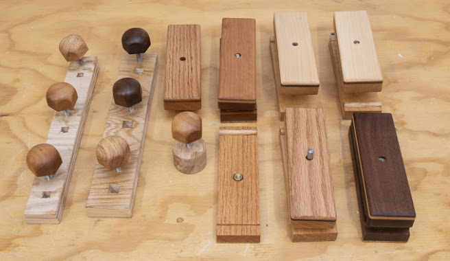
Below is what the five sanding blocks look like ready to
apply three coats of Danish Oil Finish and buff out. This type of finish is used rather than my
usual lacquer as an oil finish can be rejuvenated down the line a lot easier
than a film finish.

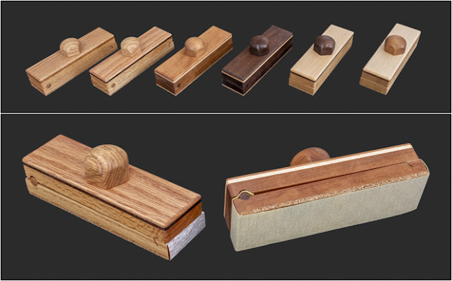
Here are the pieces with one coat of Danish Oil Finish on
them. There are seven knobs because
I made one to replace the prototype and ended up finishing the cherry one with
the crack.
With all three coats of Danish Oil completed the cork
bottom needed some attention. No matter
how careful when applying the finish invariably I got some on the cork. The top photo is typical of what
happened. As I wanted to have an
unfinished cork bottom it needed to be fixed.
Cleaning is pretty easy. a sheet of 220 grit sandpaper is clamped down
to the table saw extension and a few passes cleans it up as shown in the bottom
photo.

Once completed I built a storage case to hold them along
with some cut sandpaper. Five of the
blocks are loaded with different grits of sandpaper from 80 to 400 grit. In general, the darker the sanding block the
finer the grit. In addition, I wrote the
grit on the end of the sandpaper. This
is what it looks like and will get mounted on the peg board for easy
access.

Early on I wondered if the parts would be interchangeable between the six blocks. After giving it a try they are and if desired, the parts could be all mixed up and still work just fine. Don’t think I will do that as I like the continuity of the woods but it is interesting that it would work.
For anyone who wants to make these here is the sequence of operations along with material sizes I used.
Sanding Block Sequence
- Thickness two blanks 2” x 7” x ½”
- Thickness two blanks 2” x 7” x 1/8” (one contrasting)
- Glue thin blanks to upper base
- Cut angled notch in lower base
- Glue cork to lower base
- Cut glued stack and lower base to 6.25” length and 1.83” width
- Sand cork on lower base to 5/8” total thickness and sand smooth edges
- Clamp upper and lower bases together, drill 5/16” dowel hole centered 13/32” from edge
- Turn 5/16” dowel
- Using dowel for registration drill 5/16” hole vertically through stack and just into base for ¼” rod
- Countersink underside of stack with ½” Fostner bit 1/8” deep
- Drill 10 mm hole in base for insert & chamfer
- Temporarily install ¼"-20 brass insert & remove
- Finish sand base upper face
- Glue in dowel
- Sand excess off dowel ends
- Epoxy insert in place
- Route top edges of stack
- Final sand top stack
- Finish using DOF
Sanding Knob Sequence
- Layout knob blanks, 1 5/8”+ diameter with compass. Drill 7/32” hole 5/8” deep for rod.
- Bandsaw knob to rough circle
- Cut 1¾” long ¼”-20 threaded rod
- Thread knob hole & epoxy rod into knob blank
- Put fixture in lathe and use live center to true center
- Do not take fixture out of lathe, take chuck & fixture off lathe then put cap in fixture
- Turn to a 1 37/64” diameter cylinder
- Turn dome shape total 7/8” tall with lower ½” still a cylinder
- Take chuck off lathe, remove knob & install in jig
- Sand 6 flats with jig on disk sander, remove from jig
- Use sanding jig to sand flats to 320
- Put back on lathe fixture then using 120, 220 & 320 sandpaper feather dome & edges between flats knocking of sharp edges. At very end reverse lathe and sand with 320 to help feather both edges
- Remove from lathe fixture and break base to face surface
No comments:
Post a Comment