

With the material selection done the top jaw, bottom jaw
and cam blanks were cut a little long and to finished width and thickness. Set side by side you can easily see how the
two oaks look different.

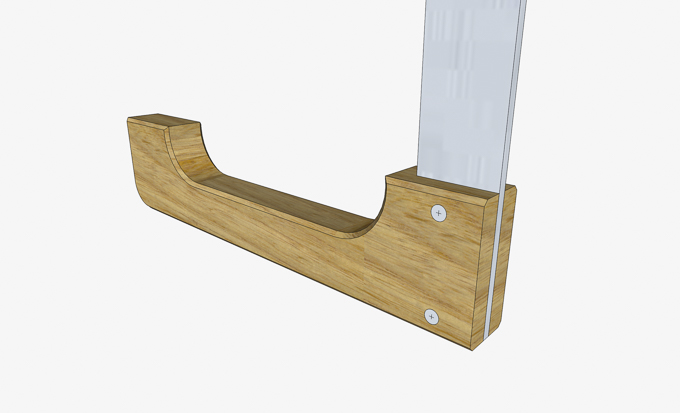
First cut is the slot at the end of the bottom jaw where
the aluminum bar will go. Here is a
rendering of how those two pieces will go together.
That’s done using the tenoning jig shown here set up and
ready to go. The detail on the right shows the outer
limits of the cut for the aluminum bar.

A shallow test cut is made then the sides are measured to
see if the cut is centered. In this case
it’s off center by three thousands of an inch and that’s just fine. I will mark the outside face on all the
pieces so when assembled the bar will be square with the jaws. Since the pieces are long if the cut was off
I could trim the piece and recut.

The final depth is then set and the slot cut in the
bottom jaws. Here you can see what the
cut piece looks like along with one in the tenoning jig. One interesting item came to light is the
fit of the aluminum bar in the just cut slot.
Even though both pieces were cut with the same table saw setup there is
a .004” difference between the width of the two. The Red Oak slips in easily and slides along
the bar with no problem while the White Oak one is a snug fit and does not
slide without a fair amount of effort.
No idea why or what caused it.

Tracing the template onto the bottom jaw is next as shown
here along with the aluminum bar set in place.

A Fostner bit is used to rough out the interior arcs in
the jaw. To eliminate any chance of
blowing out the back side of the jaw when the hole is drilled the depth of cut
is set to stop just short of breaking through.
Here you can see the small gap between the bit and the sacrificial base.

Since the bit is just cutting a partial hole, I clamped
the piece securely in place so it would not move during the cutting
process. The top photo shows the setup
and the bottom photo shows the finished cut with the thin section at the bottom
of the hole. The thin piece is cut free because the rim of the bit cuts slightly deeper than the rest so when cutting from both sides you end up with that thin piece.

To smooth the bandsawn section and the drilled arcs at
the ends the oscillating sander is used.
This is similar to the smoothing process used for the templates. The difference here is that I wanted to use a
larger drum starting with a coarser grit as this drum matches the radius of the
arc, the pieces are thicker and a lot harder material than the templates. Using a larger drum required a little
different setup than the templates.

Once the rough sanding to shape is done the sanding
sleeve is changed out to a finer grit to smooth out the cut. That’s followed by a trip back to the bandsaw
to rough out the outside arc followed up by hand sanding the cuts up through
220 grit paper. Here are the two lower
fixed jaws at this point. Just out of
curiosity I weighed the two samples since they are identical in size and found
that the White Oak is about a third heavier than the Red Oak. The extra weight is definitely not due to
moisture content as both have been setting in the storage area for years.

Work on the upper sliding jaw is next. The general shape is similar but it does have
a few detail differences.

The first step is to cut the slot for the aluminum bar
which is the same as the slot in the lower fixed jaw except it is cut a bit
deeper. Next is to cut the slot for the
cam lever that will provide the pressure to tighten the clamp. That’s done on the table saw with a ¼” wide
dado blade and a stop. The stop will
limit the length of the cut to 4”.

Here is how the stop works to limit the cut. Note that the piece is upside down and that
this slot will end up at the top of the jaw.

After that the template is used to trace the notches at
the top and bottom of the jaw. The
bottom notch is made the same way as the one in the fixed lower jaw. The one at the top is not drilled but rough
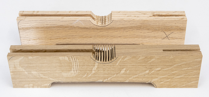
cut on the bandsaw. Since the bandsaw
blade is ½” wide it can’t cut very tight corners so rather than taking the time to
change the blade I cut a series of saw kerfs as shown in the front piece then
cut them out giving me the rough shape shown on the back jaw.
Using the same oscillating drum sander setup as with the
lower fixed jaw the notches are sanded fairly smooth then finished by hand
sanding.

Next is to drill a pilot hole for a screw that will go in
at an angle near the back of the notch.
It is to help reduce the chance that when the cam is actuated the upper jaw moving face will not get split. Below you can see how the ramp I
made for the Router Plane worked out to be just what I needed.

Cutting a slot in the upper jaw along with a 1/8” hole is
next. Below you can see the template and
the finished slot. The 1/8” hole acts to
spread the stress out across a curved surface helping to reduce the chance of
the lower part splitting when the cam applies pressure to it. I did move the hole slightly when the screw
was added which as noted above also acts to mitigate the chance of the piece
splitting. Also, on the left side the
punch is in the template for marking the center of the cam axle.

Next Up – Making the Cam, Fitting the Pins &
Finishing
No comments:
Post a Comment