
With all the pieces cut and milled for the base I now
need to go back and route a small 1/8” radius on most of the edges to soften
them. Of course, a little problem
cropped up as I was ready to do the first piece. One of the side rails had a couple of worm
holes. One of them is on the bottom of
the rail and I can live with that but the other one is one the side. When the table is done it will be on the
inside but still visible and I suppose I could leave it but don’t want to. The fix is to drill the hole out and patch it
with a matching plug. The top photo
below shows a ¼” brad point drill in the drill press centered over the worm
hole. The bottom photo shows the drilled
hole for the plug.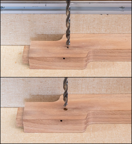
The plug is cut using a ¼” plug cutter mounted in the
drill press. The blank is from the waste
cut away to make the offset just to the right of the worm hole. Using that scrap should give me a plug that
matches the color and grain really close.
Once cut the plug is popped out of the blank and glued in
the rail. The top photo shows the plug
blank minus the plug and it glued in place.
One thing to note is the direction of the gain. The plug’s grain needs to run parallel to grain
in the rail otherwise it won’t blend in.
Voice of experience there. The
plug is cut just proud of the rail using a pull saw whose teeth have no
set. The blue tape gives me a visual if
I start to cut a little deep. The bottom
photo shows the plug cut off.
Here is what the rail looks like with the completed plug
sanded smooth with the rail’s surface along with the pull saw used to cut the
plug off flush.
With that detour done I can work on the routing. Below is the bit set in the router table so
the bottom corner of the bit’s arc is flush with the table. On the rail the top right edge has been
routed while the three others still need to be done. Since all the table base parts have most of
their edges routed there are a lot of edges to do.
The legs have a quirk on one edge. Three of the edges get a full-length routed
edge. However, the inside corner only
gets routed up to the bottom of the lower rail.
The stopping point is circled in red.
The stopping point is eyeballed short at the router table
and a pencil line is marked on the fence.
The edge is routed to see how much it is actually short then a new line
is made and the edge routed again. A
couple of tries gets it close. Once
that’s done and the side rail is set in place some hand work is needed to make
a smooth transition as illustrated in the top photo. That’s done with a small fine-toothed file
then the leg is finish sanded to 220 grit sandpaper and any touchup work at the
intersection is done. The file and
finished intersection are shown in the bottom photo.
Most of the edge routing is pretty straightforward I just
need to be careful to note which edges are routed and which are not. Routing the front/back rails requires a
two-step process because of the notch in its top. First is to set the edge of the bearing flush
with the router table fence. Without the
fence the bearing would drop into the notch and round over the notch’s edges
which need to be kept square. 
To route the rest of the rail the fence is moved out of
the way to provide access to the bottom of the notches and the tapered ends.
The last bit of work on the base involves making
provisions for attaching the side rails to the wood top, that is if I go with a
wood top instead of a stone top.
Attaching a wood top is not as simple as either gluing it down or
running some screws up from inside through the rails into the top. That’s because of the way wood moves when
exposed to different humidity levels. A
solid oak top expands or contracts across the grain in response to the humidity
change as do the rails while the change along a piece’s length is
negligible. The problem is the rails are
90 degrees to the top. That means the
top wants to expand and contract while the rails don’t. If the top is solidly attached to the rails
the forces can be enough to split the top when it moves and that’s not a good
plan. To get around this a single screw
is run through the center of the side rail into the top to keep it in
place. Then to allow for the top to
expand and contract about its center line the end holes in the side rail are
really slots with the screws just pulled down snug. This leaves the top free to expand or
contract and not split as the humidity changes.
Once the slots are laid out the center point is marked with a punch, a
hole is drilled at each end and one between them. Here in the top photo, you can see the layout
punch marks for the alignment hole in the center along with the slots at either
end. The tool at the bottom of the top
photo is my spring-loaded punch. The
lower photo is a close-up and you can easily see the centering punch marks.
After the holes are drilled the interior edges of the
slots are cleaned up using a Dremel tool with a spiral cutter then finished
with flat and round rifflers. This is
what the slots and the center hole look like completed.
Here is what a set of rifflers look like. If you are interested, this link will take you
to the project, I did to make their handles and build their storage case.
No comments:
Post a Comment