
Laying out the handle is done with a half-pattern. It’s used to draw the left half then flipped
over to draw the right half. This gives
me a perfectly symmetrical layout. While
the original piece had a lot of cracks and some knots the early planning I did
worked around them.
Cutting the handle out is done on the bandsaw. Because I have a ½” wide blade on the bandsaw
I need to make some relief cuts as the inside curves are too tight for that
wide a blade to make. Those cuts are
shown in the top photo. I could have
changed the blade from the ½” to ¼” which would have let me make the
cuts in one pass. However, it takes a
while to change the blade and reset the guides so for three handles it’s not
worth it. The bottom photo shows how the
handle’s larger outside curves can be cut in one pass.
Once the handle is cut out the outside face gets smoothed
using the large disk sander. The inset
is a closer view that shows the sanding marks.
Because the sandpaper is pretty coarse some additional sanding with the
¼ sheet sander will be needed to get rid of those marks. 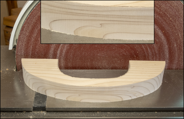
Sanding the inside curve of the handle is done using the
oscillating drum sander. Fortunately,
the drum has different grit sleeves available so I can start with a coarse grit
for shaping then switch to a finer grit which gives a pretty good finish.
Making the base plate out of ¾” thick oak plywood is
next. All went well until the final rip
on the last base. That cut edge had a
void in one of the plies as shown in the top photo. If I had another piece of the plywood I would
have just tossed this one but the only pieces available are good sized and I
didn’t want to take a small piece out of them.
The fix is to glue in a patch.
That starts by using the table saw to cut a slot as wide and deep as the
void the full length of the piece. The
setup to do that is shown in the bottom photo using the cutoff scrap from the
bases.
The slot gets filled with a spacer made from the cutoff
when the handle blank got ripped on the bandsaw. It was just a tiny bit too thick but was
milled to just the right thickness using the thickness sander. After being rough cut to width and length it
gets glued in the slot. Here the top
photo shows what it looks like ready to be trimmed on the table saw and the
bottom photo shows the setup for ripping.
The ends are cut using the chop saw.
With the ends and the edge trimmed you can’t even tell
there was a patch used. The bottom two
photos is a closer view with the patch identified by the red arrow.
Clipping the corners of the base is next using an
adjustable jig set at 45 degrees. The
top photo is with the jig and saw set up and ready to go. The bottom photo is after one corner has been
cut. Flipping the board end for end then top to bottom gets all four corners
clipped with one setup.
Next the handle gets centered on the top and its feet get
traced onto the base. The positions of
the screws that will be used to attach the two get laid out followed by
drilling pilot holes for the screws.
That’s been done in the top left photo.
The right photo shows the base flipped over and a stepped drill bit
being used to countersink the hole. This
will allow the screws to be run in anchoring the handle in place while being below
the surface of the base. I like using
Kreg® screws (bottom left) because the head has a square drive rather than a
Phillips or slot. The screw is also case
hardened and has a self-tapping tip so it’s less likely to spit the wood when
driven in.

Rounding the edges of the handle is next. That’s done with the router and a round over
bit. Here the top face has been done
along with the outer edge of the face that’s down. The bottom inside edge still has to be done.
After the handle’s edges are routed it gets finish sanded
along with the base. The base also gets
its top edges softened. Last before
finishing is to mask the areas where the handle and base come together. The tape will keep those areas clear of
finish when sprayed. I want bare wood
where the handle and base come together so there will be a good glue joint.
Spraying the parts with lacquer is next. The photo below shows most of the items used;
lacquer thinner, lacquer and various mixing bottles. There is also protective gear consisting of a
mask with N100 filter cartridges that filter out both organic and acid vapors
and gloves. 
This photo shows the spraying setup where a base is on
yellow painter’s triangles set on a lazy susan so the part can be easily turned
to get to all sides. The handle gets
sprayed while I hold on to it using the screw.
Wrapped around the screw is wire used to hang the handle from a
support. After the second coat of
lacquer is applied the surface gets sanded with 600 grit paper to remove any
dust nibs followed by the final finish coat.
After letting the finish cure for a few days, the pieces
are wet sanded with an 8,000-grit pad and the masking tape is removed. Below is a before the tape is removed and an after. It’s easy to tell where the wood
is still unfinished. The letter "C" on the right is used to match the handle to the proper base.

After curing the tape gets removed and the sandpaper is
cut flush with the base’s edges. Below
are the three completed push blocks. The
top left one is different than the other two in that it has a small lip on the left
end which provides a positive stop to the trailing end of the piece being
jointed. The two on the right are the
same except the bottom one is a little narrower.
Last is to make and mount a small shelf on the jointer to
hold the push blocks. It’s made out of
¼” plywood with a ½ square rim of oak.
Here is what that looks like.
This competes the work on and related to the jointer. My only problem is I still have not found a good home for it in the shop. So, for now it gets moved around depending on what equipment is being used.
Next Up – Wood Hold Down - #1 The Beginning
Below is a drawing of the Hold Down.
No comments:
Post a Comment