Router Plane

Showing posts with label Shop Stuff. Show all posts

Monday, October 17, 2022

Jointer - #3 The Handle, Finishing & Assembly

Laying out the handle is done with a half-pattern.  It’s used to draw the left half then flipped over to draw the right half.  This gives me a perfectly symmetrical layout.  While the original piece had a lot of cracks and some knots the early planning I did worked around them.

Cutting the handle out is done on the bandsaw.  Because I have a ½” wide blade on the bandsaw I need to make some relief cuts as the inside curves are too tight for that wide a blade to make.  Those cuts are shown in the top photo.  I could have changed the blade from the ½” to ¼” which would have let me make the cuts in one pass.  However, it takes a while to change the blade and reset the guides so for three handles it’s not worth it.  The bottom photo shows how the handle’s larger outside curves can be cut in one pass.

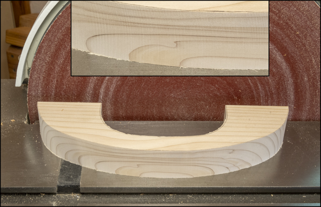
Once the handle is cut out the outside face gets smoothed using the large disk sander.  The inset is a closer view that shows the sanding marks.  Because the sandpaper is pretty coarse some additional sanding with the ¼ sheet sander will be needed to get rid of those marks. 
Sanding the inside curve of the handle is done using the oscillating drum sander.  Fortunately, the drum has different grit sleeves available so I can start with a coarse grit for shaping then switch to a finer grit which gives a pretty good finish.

Making the base plate out of ¾” thick oak plywood is next.  All went well until the final rip on the last base.  That cut edge had a void in one of the plies as shown in the top photo.  If I had another piece of the plywood I would have just tossed this one but the only pieces available are good sized and I didn’t want to take a small piece out of them.  The fix is to glue in a patch.  That starts by using the table saw to cut a slot as wide and deep as the void the full length of the piece.  The setup to do that is shown in the bottom photo using the cutoff scrap from the bases.

The slot gets filled with a spacer made from the cutoff when the handle blank got ripped on the bandsaw.  It was just a tiny bit too thick but was milled to just the right thickness using the thickness sander.  After being rough cut to width and length it gets glued in the slot.  Here the top photo shows what it looks like ready to be trimmed on the table saw and the bottom photo shows the setup for ripping.  The ends are cut using the chop saw.

With the ends and the edge trimmed you can’t even tell there was a patch used.  The bottom two photos is a closer view with the patch identified by the red arrow.

Clipping the corners of the base is next using an adjustable jig set at 45 degrees.  The top photo is with the jig and saw set up and ready to go.  The bottom photo is after one corner has been cut. Flipping the board end for end then top to bottom gets all four corners clipped with one setup.

Next the handle gets centered on the top and its feet get traced onto the base.  The positions of the screws that will be used to attach the two get laid out followed by drilling pilot holes for the screws.  That’s been done in the top left photo.  The right photo shows the base flipped over and a stepped drill bit being used to countersink the hole.  This will allow the screws to be run in anchoring the handle in place while being below the surface of the base.  I like using Kreg® screws (bottom left) because the head has a square drive rather than a Phillips or slot.  The screw is also case hardened and has a self-tapping tip so it’s less likely to spit the wood when driven in.

Here is a side and bottom view of the push block with the handle screwed in place.  After this test fit the piece is disassembled so work can continue.

Rounding the edges of the handle is next.  That’s done with the router and a round over bit.  Here the top face has been done along with the outer edge of the face that’s down.  The bottom inside edge still has to be done.

After the handle’s edges are routed it gets finish sanded along with the base.  The base also gets its top edges softened.  Last before finishing is to mask the areas where the handle and base come together.  The tape will keep those areas clear of finish when sprayed.  I want bare wood where the handle and base come together so there will be a good glue joint.

Spraying the parts with lacquer is next.  The photo below shows most of the items used; lacquer thinner, lacquer and various mixing bottles.  There is also protective gear consisting of a mask with N100 filter cartridges that filter out both organic and acid vapors and gloves. 

This photo shows the spraying setup where a base is on yellow painter’s triangles set on a lazy susan so the part can be easily turned to get to all sides.  The handle gets sprayed while I hold on to it using the screw.  Wrapped around the screw is wire used to hang the handle from a support.  After the second coat of lacquer is applied the surface gets sanded with 600 grit paper to remove any dust nibs followed by the final finish coat.

After letting the finish cure for a few days, the pieces are wet sanded with an 8,000-grit pad and the masking tape is removed.  Below is a before the tape is removed and an after.  It’s easy to tell where the wood is still unfinished.  The letter "C" on the right is used to match the handle to the proper base.

Assembly consists of gluing the handle to the base and running in four screws.  Last, is to glue a slightly oversize piece of 120-grit sandpaper to the base using spray adhesive.  The sandpaper provides some grip between the push block and the piece to be jointed.  Once applied the push block is put in a vice to put pressure on the glue joint overnight.  In the photo you can see masking tape around the base’s bottom.  This keeps the adhesive overspray off that edge.

After curing the tape gets removed and the sandpaper is cut flush with the base’s edges.  Below are the three completed push blocks.  The top left one is different than the other two in that it has a small lip on the left end which provides a positive stop to the trailing end of the piece being jointed.  The two on the right are the same except the bottom one is a little narrower.

Last is to make and mount a small shelf on the jointer to hold the push blocks.  It’s made out of ¼” plywood with a ½ square rim of oak.   Here is what that looks like.

This competes the work on and related to the jointer.  My only problem is I still have not found a good home for it in the shop.  So, for now it gets moved around depending on what equipment is being used.

Next Up – Wood Hold Down - #1 The Beginning 

Below is a drawing of the Hold Down.


Monday, October 10, 2022

Jointer - #2 Finishing Dust Collector Adapter & Starting Push Blocks

Making the hardware to attach the adapter to the jointer is next.  At the top I used a couple of steel splicing plates left over from a previous project that only needed to be flattened, one mounting hole added and painted.  The bottom gets attached to the jointer’s steel frame base using some long machine screws that go into some threaded holes on the jointer base I added.  The top photo below shows the front of the finished adapter along with the mounting hardware.  The bottom photo shows the back of the adapter.  The black is a piece of foam that will seal the adapter against the rail’s stand and the shallow recess at the top is for the chute’s cover.

Here is the adapter mounted on the jointer with the vacuum hose connected.Along with the jointer came a pair of push blocks that are used to keep one’s hands away from the cutterhead which spins at 4,800 RPM’s with the knives making 14,400 cuts per minute.  To me the push blocks are an essential piece of safety gear.  This is from family experience as when my dad was young, he slipped and lost a part of one of his fingers on a jointer.  These blocks are OK but I wanted ones that are a little longer, wider and have larger handles for more protection.

I decided to make three blocks not because I have three hands but to make two who’s bases are flat plus one with a stop at the back to grab the end of the piece to be jointed.  No drawings for these as they are going to be designed on the fly depending on what materials I have available.  Two of the bases will be made out of ¾” oak plywood 4” wide and 11” long while the other one also from out of ¾” oak plywood will be bit narrower.  The handles will be made from scraps of 2x6 construction lumber salvaged from the Master Bath Remodel.  I am using these since they were put in place in the mid 1990’s and have been drying for well over 25 years so they should be thoroughly dry and stable.  They are however cupped and twisted.  The photo below shows the cup, twist and cracking pretty well.  Since I had a paper cutout of the final handle, I moved it around on the blanks so they are free of knots, cracks and splits.

Here the bandsaw has been used to cut off the worst part of the blank which also helps to reduce the cup although it really does not help the twist much.

This is what the jointer and shop-vac look like set up and ready to go.  They are plugged into two different electrical circuits because the jointer needs a 20 amp breaker and the shop-vac draws 11 amps.

In the top photo looking down on the jointer the handle blank is set with the to be jointed face up.  Since I am not in a rush to flatten the board, the jointer is set up to take off only 1/32” per pass.  That amount does not bog the machine down so it’s easier on the equipment, there is less chance of a catch particularly as there are a couple of knots plus I end up taking no more off than absolutely needed.  The bottom photo shows the face flat and true.  This gives me one reference surface that will be used to bring the other faces square and parallel to it.  In use the jointer worked great, smooth effortless cuts and the dust collection captured all the chips.

The top photo shows the completed reference face to be use used to joint an adjoining edge square to it.  This is one reason I took the time to make sure the fence is square with the bed.  Squaring the edge is done by holding the reference face against the fence and running across the jointer until the surface has been cut along its full length and width.  When that’s done, I have one face and one edge flat and square with each other.  The top bottom photo shows the two squared edges.

Next is to bring the second wide face parallel and flat with the one previously jointed.  That can’t be done on the jointer because while it will make the second face flat it wouldn’t necessarily be parallel with the first face.  Either a planer or the thickness sander will work since they are designed to make opposite faces parallel.  Since this is a small piece and there is not a lot of material to remove, I will use the sander since it’s easier for me to set up and use than the planer.  Shown is the second wide flattened face. 

With both wide faces straight and parallel plus one edge straight and square with the faces last is to make the remaining edge straight and square with the others.  That’s done with the tablesaw.  Here it’s set to make a cut closer to the final width needed for the handle.

Ripping the blank to rough thickness on the bandsaw is next.  A marking gauge is used to give me a line to cut to.  A pivot point attached to a magnetic fence is set up to guide the thickness.  Here is the handle blank and the cutoff.

The bandsaw leaves a fair cut but to smooth it out it’s back to the thickness sander.  Here in the top photo, you can see where I have pencil marked the surface.  That along with the bandsawn marks will allow me to gauge how the flattening is going and when to stop.  The bottom photo is of the finished piece.  All in all, it’s a little bit of work to take a piece in as bad a shape as this was and make a flat and square piece of wood.  However, in practice the individual steps move right along.

Next Up – The Handle, Finishing & Assembly

Monday, October 3, 2022

Jointer - #1 A Gift, Rust Removal, Alignment & Starting Dust Collector Adapter

Part way through making the Planer Sled I got a note from a friend who follows this blog.  He had a barely used Delta 6” jointer on a mobile base that he gifted to me.  After picking it up I stored it in the garage until I had the time to rearrange the shop a bit to give it a home, which is now.  While the jointer is in almost brand-new shape after setting unused for a few years there were a few things I wanted to address before using it.  One was some rust on the machined tables and fence.  The other was that while it had an enclosed dust chute to direct the chips to the floor there was no way to hook it up to my shop-vac to capture the dust and for chip collection. 

The first thing to tackle is the rust.  One benefit of living in the desert is the low humidity which minimizes the accumulation of rust on unfinished machined cast iron surfaces.  Most of the rust was just a light bit on the machined tables and the fence.  There was a bit more rust where the fence sat on the infeed and outfeed tables due to the accumulation of chips that were stuck there.  Not bad, but it did take a little more elbow grease to clean up.  Unfortunately, I forgot to take a photo of the jointer before starting work so the first photos are after it was already disassembled and the rust had been removed.  Below the top image is of whole jointer.  The middle image is of the outfeed table and the bottom image is the infeed table.

Cleaning up the fence is next.  Below is what I use to use clean all the machined cast iron surfaces.  I start with mineral spirits (left bottle) to remove sap and the like.  Given the amount of pitch I am guessing that mostly pine or maybe cypress was jointed.  Sanding with 180 grit silicon carbide sandpaper mounted a red rubber block using WD-40 as a lubricant gets the rust off.  Once the rust is off the 180-grit paper gets changed out to 220 grit for finish sanding.  Next is to lightly spray it with the CRC 3-36 which is a lubricant and corrosion inhibitor.  It’s allowed to set a bit then wiped off.  Last is to use the Bostik GlideCote which is a high-molecular weight polymer that reduces friction.  All told it probably took about 30 to 40 minutes of work to clean and treat the surfaces.

Last bit of work is to check everything for squareness and to no surprise given the jostling during the move a couple of minor adjustments are needed.   First, is to square the fence to the table using a small steel square.

The other adjustment is to set the outfeed table so it is dead in line with the top of the knives.  This is so once the knives have made their cut the surface of the piece being cut continues in the same plane onto the outfeed table.  If they are out of alignment, it will cause problems and not give a true flat surface.  Process starts with a knife set at top dead center and a straight edge set on the outfeed table running across the cutter head.  Next the table is raised or lowered until the cutter head just touches the straight edge. The photos below show what this looks like.

Here the jointer is all put back together with all the adjustments made ready to go.  With that done I made a couple of test cuts and it works great – smooth, square and even.  However, it does generate a whole lot of chips that end up on the floor so before putting it into regular use I need to make an adapter that will divert the chips coming out of the chute and allow me to connect the vacuum to collect them.

First, is to fit a base piece of ¾ plywood to cover the chute then glue another piece of ¾” plywood on top of that for the vacuum hose to connect to.  Here is what that looks like glued up.  In the center of the top piece, you can see a couple of screws.  They were located and temporarily run in before gluing the two pieces together to assure that the two pieces would not slide out of alignment when clamped.  They then get removed, glue applied, the screws run in and the clamps added.

As you can see in the glued-up photo above the top block corners are clipped to get rid of sharp corners.  That was done using a jig on the table saw.  In the top photo the setup is being done with a 45-degree triangle.  The bottom photo shows how the cut is made.  Once the four corners are cut the top edge gets rounded over using the router and a small roundover bit.

After the glue dries the clamps and the screws get removed.  Next using the drill press a hole is drilled through both pieces which will provide a place to attach the vacuum hose.   Here you can see the drilled hole along with three concentric lines.  They are there to guide the hole enlargement and its tapering because the bit used is too small but it's the closest I have to what’s needed without making the hole too big. 

The oscillating drum sander is used to enlarge and taper the hole.  The taper is accomplished by tilting the table a couple of degrees and rotating the workpiece so the sanded face is always toward the front.  When getting close to final size the inside of the hole is marked using a pencil to confirm the full length of the hole gets a taper.  Now it’s just gradually sanding to enlarge the hole until the hose has a friction fit.  Last bit of woodworking is using the big disk sander clip the base’s corners knocking off the sharp corner then hand sand the remaining hard edges to soften them.  After that the adapter gets finished with three coats of lacquer sprayed on.

Next Up – Finishing Dust Collector Adapter & Starting Push Blocks