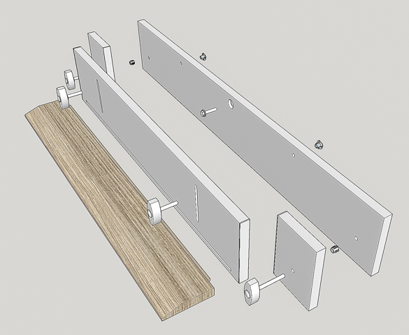
In operation the “L” fence assembly slides up and down
between a pair of end guide blocks. To
make the sliding operation smooth the ends of the adjustable backer and its
mating edge on the guide blocks get faced with a smooth plastic laminate. The drawing below has red arrows pointing to
the faces that will get the laminate.
These laminate strips are made from a cutoff left over
from a previous project. Because the
laminate is thin and brittle to reduce the chance of breakage when being cut a
sandwich is made with a couple of sacrificial pieces above and below the
laminate like this.
Once the rough blank is cut next is cutting the slightly
oversize narrow strips that get glued to the ends of the pieces. This is what the sandwich looks like with the
top piece removed. Here the first strip
is used to support the left edge of the top sandwich piece so it does not rock
when the cut is being made.
The just cut strips of laminate get glued to the plywood
edges using contact cement. The photos
show how they are being clamped while the cement cures. In the bottom photo the two end blocks are clamped face to face and you can see how the laminate is a little
oversized. It’s oversized because once
the contact cement is applied to both surfaces and allowed to set when you put
the laminate on the plywood it grabs instantly and no adjustment is
possible. Once cured the laminate will
get trimmed to fit the plywood.
Trimming the laminate is done using the small router with
a straight bit that has a guide bearing on the end guiding the laminate cut flush with the oak plywood. Below the
top photo shows the router, its bit and where just a short section has been
trimmed flush. The inset photo is a
close-up view of the router bit. The bottom photo is after all the laminate has
been cut flush with the oak. Because the
just cut laminate edge is sharp, I need to break the edge with some 220-grit
sandpaper.
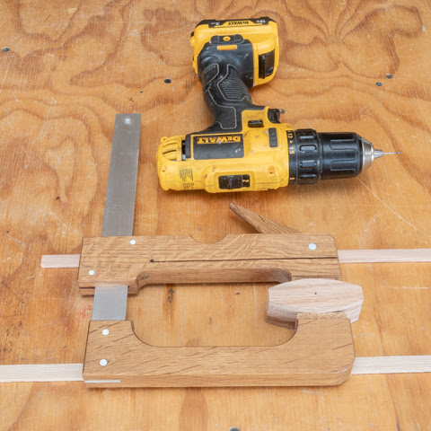
Drilling mounting holes for the screws is next. That’s done on the drill press with a bit
that cuts both the pilot hole for the for the screw along with a countersink
for the head. The insert photo is a
closer look at the bit itself without the stop collar.
Once the holes are drilled, the guide blocks get attached
to the backer board. If you look
closely, you can see where the blocks are a little long extending past the ends
of the backer board. That’s done so once
they are glued and screwed in place, they can be trimmed to final length using
the chop saw for a perfectly flush end.
I started by attaching the right one first. After that the adjustable part of the jig
gets set in place then the left block is brought up tight enough so the adjusting
assembly can move easily but not loose enough to wobble. The goal is to have the a fit where the piece
moves easily but snug enough so the blocks keep the piece parallel to the
bottom of the jig.
Next is to make four knobs shown in the drawing
below. Two are used to attach the “L”
fence to the table saw’s rip fence straddling assembly and two are used with
the adjustable part of the “L” fence. I
start by taking some thin pieces left over from resawing oak for other projects
and gluing up three layers so the grain in the center piece is at 90 degrees to
the face layers, just like plywood. This
will give the knobs some additional strength to resist splitting along the
knob’s long dimension. You can see the
three layers in the left photo below.
The lower right photo shows how the piece will get cut into six knob
blanks including the saw kerfs.
After cutting the blanks out a ¼” square hole (mortise) gets cut
partway through the knob blank for the square part of the carriage bolt to fit
in. Below in the left photo you can see
how the threads in the bolt transition into a square shoulder underneath the
bolt’s head. The right photo shows the
mortising machine setup used to make the partial depth square hole with the
mortise just started.
After the square mortise gets made a hole for the
threaded part of the bolt is drilled through the blank.
Laying out the curved sides of the knob is next and to do
that the pattern in bolted to the knob blank and it’s outline traced. Below is a side and top view of what that
looks like.
With the knob shape drawn on the top the curved edges get
made using the large disk sander. The
bottom photo is a closer view where the closest edge is almost to the line but
not quite. The face up against the
sander is just getting started. I don’t
completely finish one side before starting on the second side because as the
piece gets sanded the wood heats up and can burn. Working back and forth gives the sides a
chance to cool off a little reducing the chance of burning the edge while
sanding.
When that’s done it’s time to route a small radius on the
top and bottom edges softening them. In
the bottom photo you can see where the top has been finished and the bottom is
ready to go. When the top and bottom
routing is completed, the vertical edges will still be sharp.
Rounding those sharp edges is next and that’s done using
three hand sanding blocks loaded with different grits of paper. Last is some hand sanding using a small piece
of 220 grit sandpaper to knock off the points where the horizontal and vertical
rounded edges intersect plus do any blending as needed where the routed edges
meet the flat surfaces. The photo below
shows each of the four steps needed to go from the mortised and drilled blank
to a shaped knob. These will get set
aside for a while before the carriage bolts get installed.
Next Up – “T”-nut & Threaded Insert Installs – Finishing