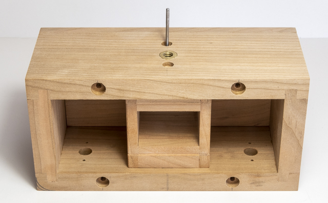
Once the screw’s location is marked, I can drill its
pilot hole. The blue tape is my depth
gauge so I don’t drill through the film box.
The other larger drill will be used to enlarge the hole in the camera
body so the screw floats in the camera body and its threads do not bite into
the wood until it gets to the pilot hole in the film box. That way I can be sure the film box will be
pulled tight up against the bottom of the camera body.
Here’s what the pinhole lens, the film box and the camera
body look like assembled. If you look at the upper right hand corner of the camera there are a couple of arcs marked in pencil. That was me trying to decide which radius to use on the corners.
To make the camera feel a little softer to the touch the
edges will be rounded using the router but before that there is a little work
to be done. Both the front and back were
cut just slightly oversize and they need to be sanded flush with the camera
body. That’s done by using three
different grits of sandpaper, 120, 220 and 320 clamped down. The camera is run across the 120 paper until
the surfaces are flush. Sanding is then
done with the 220 to get rid of the 120 scratches then on to the 320 until the
surface is smooth. The blue tape was
applied after sanding and the reason for that is explained below.
Just one more thing needs to be done before routing. Since the front is glued on it’s not going to move but the back comes off so to hold it in place, I used the blue tape to securely hold it. The four corners are rounded over with a 3/8” radius round over bit. As the routing is all end grain which is prone to chipping out several passes were made raising the bit a little at a time. Here you can see the completed routing. The routed edge on the left has some burn marks. That’s fairly common on cherry as it burns pretty easily particularly when routing end grain. Note the right routed edge does not have the burn marks and that’s because it’s been almost finish sanded using the three grits of sandpaper described above.
That takes care of the corners. Next are the front and back face edges. They also get routed but with a much smaller
1/8” radius bit. Same process a above
except the final sanding goes one step farther with 400 grit paper on all the
edges and faces. The front view now
presents a softer more comfortable appearance and feel.
The same is true for the back although there is still some work to be done on the edges that are visible when the back is removed.
Finishing the shutter assembly is next. That entails adding the remaining finger
recess to the shutter slider, cutting the pieces to length plus softening all
the exposed edges. That softening was
the most time-consuming part of this work.
I know it may sound a little strange but the edges are really sharp. Enough so it’s not that hard to cut yourself
on them. So, in order for the camera to
feel comfortable in use that edge needs to be removed. In other projects I have used both chamfers
and rounding. Because the other edges
are rounded that’s what will be done here.
The rounding amount is small only about 1/32” which is accomplished
using 220 and 320 grit sandpaper. In
order to see in enough detail to create a consistent radius the jeweler’s
magnifier, a lot of light and about an hour’s time are needed. This is what the finished assembly looks like
when the shutter is closed.
When the shutter is open the slider is flush with the edge giving tactile feedback that it is set at the correct place.
Because the back needs to be securely held on there will
be 8 rare earth magnets installed to accomplish that. In the photo of the back up a couple
paragraphs you can see that there are no provisions for a finger or thumb to
get a grip when it comes time to remove the back to load or change film. Fixing that is next. It’s done using the oscillating drum sander
along with a jig that holds the camera body at an angle. If you are interested the basis of the jig is
from the Router Plane project that I had kept.
A fence clamped to the sander’s table keeps the jig aligned with the
center line of the oscillating drum.
This is a closer view of how the finger grip space is made. When I get close to the finished depth the coarse sanding tube is replaced with a fine grit one for a better finish. It’s not the final finish, that’s done by hand sanding down to 320 grit.
Here is the body and the back fitted together where the
finger grip inset can be easily seen.
All the hard edges that can be touched have now been rounded. That includes the edges on the back that are
visible plus the ones inside. The same
method using the jeweler’s magnifier, a lot of light plus 220 and 320 grit
sandpaper is used.
Next Up – Installing the Shutter, Finishing & Final
Assembly


No comments:
Post a Comment