Router Plane

Thursday, May 7, 2020

Wood Body Pinhole Camera - #3 Ripping to Thickness & Changing Bandsaw Blade

Ripping the boards down to the various thickness required are next.  That’s done on the bandsaw.  Here is the setup ready to go.

These are part of the rough-cut pieces ready to be run through the thickness sander.  As you can see there are some burned areas left by the bandsaw blade.  In looking at the sawdust it also shows signs of being a little burned.  This has been going on for a little while so I think it’s time to retire this blade and put on a new one. 

Ever wonder how to change a bandsaw blade?  Well, here is the way I go about it.  By the time I am done you will see why I use the ½” blade almost all the time and don’t change to a different size frequently.

The photo on the left is how I keep the bandsaw ready to go.  The photo on the right has the light and magnetic fences stored on the bandsaw taken off and the doors open.  If you are wondering what the parts are in the bottom right, they are the old blade guides the saw originally came with.

Next is to remove tension from the blade.  I typically do this after I get done with the saw for the day but because it had just been in use the blade was tensioned.  The white round zero clearance throat plate has also been taken out.  The guides near the top of the photo have been loosened and pulled back from the blade along with a second set under the table.   On the right circled in red is a tapered bolt-pin that still needs to be removed.  Its purpose it to keep the cast iron table flat on both sides of the slot.  The slot is where the blade will come out. 

Cleaning the tool is next.  I blow or vacuum all the dust off inside and out.  The old blade is removed, set aside then the wheels are cleaned and the bearings checked along with the other moving parts. 


A bandsaw blade comes coiled up similar to this only in a tighter coil.  Unwinding the blade can be fun.  Nothing like playing with a 133” long piece of coiled spring steel with 399 razor sharp points just ready to rip you to shreds.  Blades less than ½” wide are not too bad to work with.  This blade at ½” wide is OK as long as your careful but I have a 1” wide blade that is another story.  When it’s time to uncoil it, I have been known to go outside in the yard, throw it up in the air then run away while it uncoils and tries to eat me.

Once uncoiled the blade in installed in the saw, tension slowly added, the tracking checked and the adjustment of the guides can begin.  Here is what the adjusted guides look like.

The first step is to set the guides on either side of the blade just behind the gullet of the teeth.  With that done the top guide that’s behind the blade is set so there is just a tiny gap between it and the blade.  The top photo shows that done.  Next is setting the tiny gap between the side wheels and the blade.  You can use a sheet or two of paper but I just eyeball it.  When adjusted correctly and the saw running the wheels do not spin until pressure is applied to the blade and cutting begins.

As mentioned earlier there is a second set of guides under the table that need to be adjusted just like the set I just did only with a lot less room to work and it’s hard to see what you are doing. 

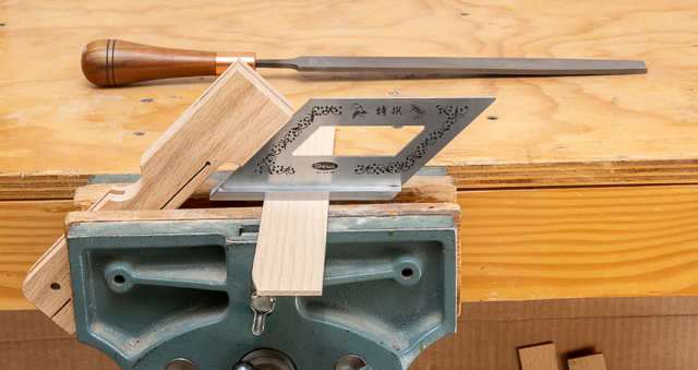
Two things remain before I can call it done.  A test cut is made, here a scrap of quarter sawn white oak is used and the results speak for themselves.  A nice even smooth burn free cut even at the bottom where the cut was made through a knot.  The last thing is to coil up the old blade and set it aside for a backup in case this one breaks or I need to cut some wood of questionable origin that might have a surprise rock or nail buried inside. 

Once all the pieces have been run through the thickness sander, I go through deciding which piece to use for what and laying the blanks out working around any flaws.  Speaking of flaws this is the piece of walnut that will be used to make the knobs.  The problem areas that I need to stay away from are circled in white.  The clean part at the top above the horizontal line is what I will cut off and use.

This is the final layout with each piece marked and labeled.  There are some just noted as "test".  They are for just that, testing machine setups and joint fitting.  They are also big enough that I can make a replacement if an irreversible problem comes up or something goes wrong and I have to start over on a part.

Cutting the dado joints in the top and bottom are first.  Here is how the top, bottom and sides will go together.

There are a couple of ways I cut dados.  Using a table saw with a stacked dado blade is one way or using a router is the other.  For these a router will be used.  That’s because since the joints will be exposed, I want an absolutely flat bottom and square corners.  My dado blade cuts a pretty flat bottom but because of the way some of the teeth are ground their points leave a tiny little angled cut line where the side meets the bottom.  You can see the different teeth in the left photo.  A router on the other hand cuts a flat bottom with a sharp square corner.  The photo on the right has the left dado cut with a router and the one on the right is cut with the table saw showing the tiny little angled cut line.  Both are ¼” wide and deep.


Next Up – Routing Dados, Tenons, Machining Top & Bottom

Thursday, April 30, 2020

Wood Body Pinhole Camera - #2 Film Take-up Spool, Detail Drawings & Selecting Wood

With the pinhole lens, the shutter and the film can winder done the last piece to resolve is the winding or take-up side of the film management.  Rob and I had discussed a number of ways to attach the film and wind it each with their advantages and disadvantages.  However, none of them really stood out as the optimum solution.  Rob ended up taking apart a regular film can wasting the film to get to the spool and brought it by to see what I could do with it.

However, before I get into that below are a couple of photos, we took using the pinhole lens mounted on a digital camera before I cut it apart (the lens, not the camera ðŸ˜Š).  This one is of the prototype we have been using to test out the different parts. 


Here we were outside working to establish the angle of view.  There is a little flare but that is probably due to us shooting into the sun.

Back to the take-up spool.  After some experimentation a straight forward fairly simple method and assembly came together that looks like it will work.  Here is the end result with the film loaded and wound onto the take-up spool.

There are two items key to making this work.  First is to modify the film by cutting a small notch in the film leader.  That is shown below where you can see at the lower right of the film leader a small rectangle has been cut away.

Second is when I looked closely at the film spool there in the center slot were a few barbs that pinched the film holding it in place.  They held the film tight enough to allow it to be wound a couple of revolutions firmly securing it while allowing the film to be rewound back into the film can.  Here is the take up spool when the film is just starting to be wound.

With all the identified problems resolved it was back to the model to incorporate all of them into one final version.  The revisions started with the measured lens to film plane distance and worked out from there.  In the end every one of the pieces were revised and or moved.  Here is what the finished 3D model looks like.


The completed model represents the overall look of the project but the two exploded views below give an idea of all the pieces that will go into the finished product.

Now that the model is done or as least as much as can be until I get into the actual build it’s time to add dimensions and there a lot of them.  The model is set up with each piece on a separate layer.  What that means is if all the layers are turned off except for say the top that’s all I see.  Doing that makes it easy to concentrate on getting all the required dimensions on it.  Once I get a view angle that shows all the dimensions, I can print it out. 

With the top done, I can turn that layer off and turn on another layer in this case the front which makes only it visible.  Dimensions are added to it and the process continues until all the pieces are dimensioned.  Individual pieces with dimensions are printed out on their own page.  With some pieces like the front a couple of views are needed to catch everything.

I could print out all of the pieces at once and include all the needed dimensions but it gets really confusing so won’t do that.  At this point I believe most of the problems and questions that I can foresee in the project have been solved.  That’s not to say nothing will come up during the build but if or more likely when it does, I hope it’s relatively easy to resolve.  All said and done the design, revisions, discussions and testing of prototypes took the better part of a month.

First up in the build is material selection.  Rob and I had discussed varieties of wood that could be used.  Oak and mahogany were rejected as more porous than what I thought would look right.  The tropical exotics were also nixed from my concern on stability.  Regular maple as well as curly or birdseye were rejected because of a concern that as a light-colored wood it might show dirt unless a film finish like lacquer or polyurethane was used.  I was concerned about either of those finishes gassing off and reacting with the 35mm film emulsion.   We narrowed it down to cherry or walnut and as we discussed the aesthetics of the piece Rob asked for a contrasting secondary material to be used.  With that in mind we decided to use cherry for the body and walnut for the shutter assembly and winding knobs.  Both are fairly hard woods that work well and look good. 

To minimize wood movement and help keep the camera stable all the pieces selected are quarter sawn and have been in my storage area for at least 10 years so they are thoroughly dried.  Here they are.  If you look close at the front right piece of cherry it does say “WARPED”. 

That was not the only piece that needed a little help.  It and another one had a bit of twist plus one had a little cup.  A little work with the hand plane and a trip through the thickness sander flattened them out.


One of the walnut pieces still had its rough sawn edge but a few swipes with the hand plane gave me a nice straight edge to work from.

Another of the walnut pieces had its grain running diagonally across it and I wanted it parallel to the edges.  The solution is to mark a line parallel to the grain, in this case the top of the piece, then cut along the line with the bandsaw.  That’s followed by using the hand plane to smooth the cut.  Last is to take that new edge and cut a parallel edge on the table saw.


Next Up – Ripping to Thickness & Changing Bandsaw Blade

Thursday, April 23, 2020

Wood Body Pinhole Camera - #1 The Beginning

Several months ago, while I was busy with another project a friend (Rob) who belongs to the local camera club asked if I was interested in building a wood bodied pinhole camera.  Well, it was something I had never attempted but the idea intrigued me.  Once finished with the projects in progress we met for a little more in-depth discussion of what he had in mind.  After exploring several types and looking at the options we decided to pursue a camera that used 35mm film similar in concept to one made by ONDU.  

When I started working on the 3D model in SketchUp it quickly became clear that there were three items critical for us making the camera work. 
  1. Designing a method of managing the film as in winding, re-winding and holding it in place during exposure.
  2. Finding a suitable pinhole “lens” to insert into the wood body.  In the simplest terms that’s a very tiny hole in a piece of very thin metal. 
  3. Some type of shutter to control the exposure.

All of those items needed to be accomplished without getting to deep into metal work as the equipment I have for metal fabrication is very limited.  Here is the first set of prototype renderings limited to preliminary case design and some rough dimensions.  At this point none of the three critical items had any resolution.

While Rob worked to source the pinhole “lens” I started on the film management part to see about coming up with a method to hold the unexposed film in place and be able to rewind it back into the film can once exposed.  After some trial and error using MDF and plywood prototypes this setup looks like it will work well for the film can end.   A slotted shaft is glued into a turned knob that has a steel washer inlayed in its base.  A couple of rare earth magnets are countersunk into the top which will mate up with the washer in the handle holding everything in place while allowing easy removal to change the film.  At this point we were still in discussion on how to take care of the winding side of the film.

Working on the shutter came next.  Reverse engineering from what I could see on the ONDU camera I put together a fairly simple metal shutter assembly.  Unfortunately, when going through what it would take to build the machining was just beyond my shop’s capabilities.  The renderings below show an exploded view and an installed view.

My next attempt was to design a sliding shutter out of wood.  Below is what an exploded view of that looks like.  There is a central slider captured by a pair of rails that uses a combination of rare earth magnets and metal bars to hold the slider in the desired location; either open or closed.  One thing with a pin hole camera is that the exposures are long so there is no need for a fast acting style shutter.


The top rendering below shows the shutter closed and the one on the bottom shows it open.  The good news is when I built a prototype the slider was held securely in place. 

Actually, it was held in place a little too well as moving the slider was pretty hard.  The four rare earth magnets and the steel plates provided a little too much grip.  A redesign that eliminated the metal plates and one of the magnets did the trick.  The slider was held in place either open or closed depending on how the magnet in the slider piece aligned with the two in the front of the camera.  Here is the redesign.

Not long after the shutter design got resolved Rob brought by a couple of pinhole assemblies that would attach to a modern Canon digital camera.  The information that came along with the it gave an f/stop of 223 and a Focal Length of 49mm which closely matched the 49.6mm measured on the camera.  We spent some time taking photos with it to determine the angle of view so that it can be added to the camera body later.  The angle at 41° equates to a moderate wide-angle lens.  Here is what the assembly looks like.

The pinhole assembly is made up of a black plastic housing that is designed to attach to the digital camera body where a typical camera lens goes and the metal pinhole “lens” itself.  We only need the actual metal pinhole.  However, getting it separated from the plastic mounting ended up not being pretty.  After about 45 minutes of non-destructive trying to unscrew the pieces with absolutely no luck I moved on to more non-reversable methods.  What finally worked was using a Dremel tool with an abrasive cutoff wheel to split the plastic. 

Once that was done and the plastic removed, I could get a good grip on the parts and it came apart fairly easily.  Bad news was while trying to unscrew the pieces the pliers did chew up the outer edges a little. 

Cleaning that up required me to turn a wood mandrel on the lathe so that I could friction fit the piece on it to clean the outer edges up.   The photos show the piece being jammed onto the mandrel.  A flat plate applies the pressure to the piece and sets it square to the lathe’s axis. 

Once the piece is mounted square, the flat plate and tailstock are pulled back out of the way so I can carefully file the edges smooth then polish to get rid of the scratches.

The last step is to cut a couple of shallow notches in the threaded retaining ring to provide a way of gripping it to allow ease of assembly and disassembly during testing.

Since this pinhole assembly is quite a bit larger and designed differently than what I had expected the mounting method needed to revised.  Here are front and back photos of the final test piece.  In the back view the notches cut in the mounting ring are easily visible.

Also, because the pinhole assembly was much larger in diameter than expected the shutter needed to be revised.  The revisions included a wider center sliding section and the relocation of the rare earth magnets.

Next Up – Film Take-up Spool, Detail Drawings & Selecting Wood

Monday, March 30, 2020

Cam Clamp - #3 Making the Cam, Fitting the Pins & Finishing

The cam is next, the rendering shows it both installed and by itself.

When making the blanks for the cams I made them about 1/64” thicker than needed for a couple of reasons.  First, if they warped any I had some room for correction and second is to give me a little extra just in case the dado for them ended up a little wide.  Well, the pieces didn’t warp but the dado ended up being about .004” undersize.  In order for the cams to move freely they were thinned down so they are about .006” smaller than the dado.  That’s done by placing the cam blanks on a carrier then running them through the thickness sander.  The bottom photo shows the blank in the carrier.

The cam pattern is traced onto the blank, cut out on the bandsaw, rough sanded with the disk sander then hand sanded smooth.  Here is the pattern, blank and shaped cam.   It’s not completed as plans are to soften the edges with either a chamfer or radius, I just don’t know which yet.  The small hole in the cam is the same size as the marking punch which allows me to do testing for the fit.  The cam and the jaw get drilled out to ¼” next followed by the final fitting to get the right amount of travel for the pressure pad.

Routing a little chamfer on the jaws and the cam come next.  Here is how that looks while being done on the router table. 

All of the edges can be done except for the upper and lower corners where the aluminum bar goes through the end of the jaws.  They are done with a fine-tooth file.  To do that they get clamped in the bench vice at a 45-degree angle.  That allows me to use the file level and not worry about what angle it needs to be held at.  I can just concentrate on getting the right depth cut.

This is a closeup of the chamfered edges.

Measuring the aluminum rods for the pins that will secure the jaws to the aluminum bar is next.  A dial caliper is used set to the thickness of the jaws.  The sharp point of the left jaw scribes a line in the softer aluminum for the required length.  The black arrow points to the scribe mark and helps me find it when getting ready for cutting.

The rod is clamped in a metal working vice that has a couple of thin boards that act as a cushion between the vice’s jaws and the rod.  They keep the teeth in the jaw from marring the rod.  The actual cutting is done with a hacksaw.  The top photo shows the vice and rod while the bottom one shows where I have started the cut.  If you look closely you can see just a tiny bit of the black mark on the right side of the cut.  That’s how much oversize the rod is cut to allow for swaging and cleanup.


After the pin is cut then filed smooth and square it’s ready to be installed.  Below shows the prepared pin and bottom jaw.

Installation is done by lightly tapping the pin in until it’s started then driving it in place until it is a little proud on both sides.  In the photos below you can see how the pin stickes out just a tiny bit.  Next is to sit the piece pin side down on the anvil part of the vice and give the upturned pin end a good whack.  That spreads the pin just a little increasing its diameter and locks it in place.  

Once the pins are set a drop of cyanoacrylate (Super Glue) is added as insurance they won’t loosen. They are then filed smooth with the jaw’s face and sanded to remove the filing marks. 

At this point all the pieces are ready for Danish Oil finishing.  Here are what the two clamps now look like.  As you can see the cams are not yet installed.  That’s because if they were pinned in place then it would be next to impossible to finish them.  Once finished the ¼” pins will be cut and installed just like the others.  I do realize that the filing and sanding of the pins will probably mess the already applied oil finish up some around them.  This is not a problem because the oil finish can be reapplied easily now or in the future if the clamps get banged up and will blend in just fine.

Putting on the Danish Oil really brings the color and grain out.  This photo is after I have put on two coats.  That’s it until they have had a chance to cure for a few days and I take a close look to see if it’s time to install the handles then go back and add another coat.  In looking at the clamps the next day, they needed a third coat. 

Once that was applied and left to cure for a couple of days the axel for the cam gets cut and installed just like the other pins in the jaws.  Surprisingly when filing the axel flat the oiled finish on the jaw was hardly scratched but for uniformity, I gave it another coat of oil.  When that had cured for a couple of days it’s time to put the pieces together and add the last pin.  This pin goes at the top end of the aluminum bar to keep the upper jaw from sliding off.   It’s not very big at only 3/8” long.  The first difference is that because it’s not flush, I needed to put it in a scrap to file the end square and flat.

Because the edge of the pin is very sharp it needs to have a small chamfer added so it won’t cause problems in use.  That’ done on the lathe by chucking the pin up in a small chuck then using a file to add the chamfer.  In the photos below you can see the pin chucked up and below that on the left is the squared off pin end while on the right is after the chamfer has been added.

Drilling the hole in the top of the bar is next.  Once laid out a punch is used to make a dimple that acts as a starting point for the drill keeping it from moving around.

After the hole is drilled the pin is inserted, centered in the bar and is ready to be locked in place.  To do that a spacer the thickness the pin is expose is set on the vice/anvil.  The pin is set in a hole drilled in the spacer and the exposed pin struck with a hammer causing it to expand in the hole locking it in place.  For insurance the clamp is flipped and the other end of the pin gets the same treatment. 

There remains only one item before they are finished and that is a cork cushion on the jaws.  I had been looking around locally to no avail but found some on-line that are 12” X 12” X 3/16” thick pieces in 4-packs at a reasonable price.  That gives me about 50 times the amount of cork I need but they do the job and I can probably use them on other future projects.


Here are the clamps showing how they would clamp things together. 

All in all the build was fairly easy and did not take a lot of time.  It also put to use the leftover aluminum bars that I had.  Now they will go in the clamp rack along with the rest of my clamps.