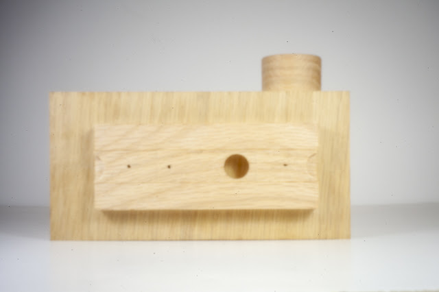
However, before I get into that below are a couple of
photos, we took using the pinhole lens mounted on a digital camera before I cut
it apart (the lens, not the camera 😊). This one is of the prototype
we have been using to test out the different parts.

Here we were outside working to establish the angle of
view. There is a little flare but that
is probably due to us shooting into the sun.
Back to the take-up spool. After some experimentation a straight forward fairly simple method and assembly came together that looks like it will work. Here is the end result with the film loaded and wound onto the take-up spool.
There are two items key to making this work. First is to modify the film by cutting a
small notch in the film leader. That is
shown below where you can see at the lower right of the film leader a small
rectangle has been cut away.
Second is when I looked closely at the film spool there
in the center slot were a few barbs that pinched the film holding it in
place. They held the film tight enough
to allow it to be wound a couple of revolutions firmly securing it while allowing
the film to be rewound back into the film can.
Here is the take up spool when the film is just starting to be wound.
With all the identified problems resolved it was back to
the model to incorporate all of them into one final version. The revisions started with the measured lens
to film plane distance and worked out from there. In the end every one of the pieces were
revised and or moved. Here is what the
finished 3D model looks like.
The completed model represents the overall look of the
project but the two exploded views below give an idea of all the pieces that will
go into the finished product.
Now that the model is done or as least as much as can be
until I get into the actual build it’s time to add dimensions and there a lot
of them. The model is set up with each
piece on a separate layer. What that
means is if all the layers are turned off except for say the top that’s all I
see. Doing that makes it easy to
concentrate on getting all the required dimensions on it. Once I get a view angle that shows all the
dimensions, I can print it out.
With the top done, I can turn that layer off and turn on
another layer in this case the front which makes only it visible. Dimensions are added to it and the process
continues until all the pieces are dimensioned.
Individual pieces with dimensions are printed out on their own
page. With some pieces like the front a
couple of views are needed to catch everything.
I could print out all of the pieces at once and include
all the needed dimensions but it gets really confusing so won’t do that. At this point I believe most of the problems
and questions that I can foresee in the project have been solved. That’s not to say nothing will come up during
the build but if or more likely when it does, I hope it’s relatively easy to
resolve. All said and done the design,
revisions, discussions and testing of prototypes took the better part of a
month.
First up in the build is material selection. Rob and I had discussed varieties of wood
that could be used. Oak and mahogany
were rejected as more porous than what I thought would look right. The tropical exotics were also nixed from my
concern on stability. Regular maple as
well as curly or birdseye were rejected because of a concern that as a
light-colored wood it might show dirt unless a film finish like lacquer or
polyurethane was used. I was concerned
about either of those finishes gassing off and reacting with the 35mm film
emulsion. We narrowed it down to cherry
or walnut and as we discussed the aesthetics of the piece Rob asked for a
contrasting secondary material to be used.
With that in mind we decided to use cherry for the body and walnut for
the shutter assembly and winding knobs.
Both are fairly hard woods that work well and look good.
To minimize wood movement and help keep the camera stable
all the pieces selected are quarter sawn and have been in my storage area for
at least 10 years so they are thoroughly dried. Here they are. If you look close at the front right piece of
cherry it does say “WARPED”.
That was not the only piece that needed a little
help. It and another one had a bit
of twist plus one had a little cup.
A little work with the hand plane and a trip through the thickness sander
flattened them out.
One of the walnut pieces still had its rough sawn edge
but a few swipes with the hand plane gave me a nice straight edge to work from.
Another of the walnut pieces had its grain running
diagonally across it and I wanted it parallel to the edges. The solution is to mark a line parallel to
the grain, in this case the top of the piece, then cut along the line with the
bandsaw. That’s followed by using the
hand plane to smooth the cut. Last is to
take that new edge and cut a parallel edge on the table saw.
Next Up – Ripping to Thickness & Changing Bandsaw
Blade


No comments:
Post a Comment