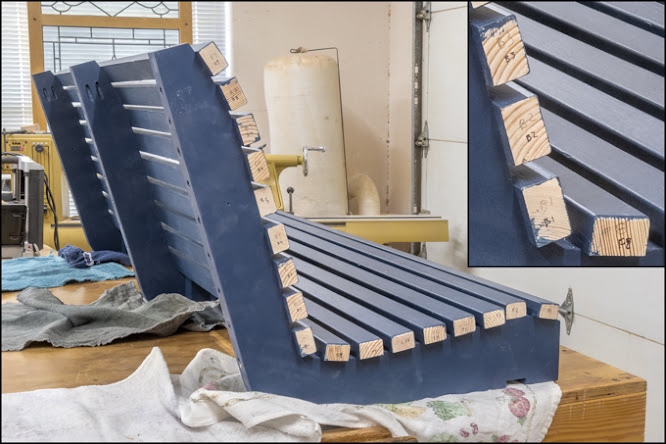
A waterproofing sealer and solid stain requiring two
coats is used for the finish. Since
there was not really a good way to hang all the pieces so all sides could be
painted at once only half of each piece gets done at a time. Giving them overnight to dry between coats
means it takes four days to finish all the parts. Here are all the almost finished pieces for
the swing. There is one end of each slat
still unpainted because that’s where their location number is written. While the slats are all the same except for
two the location of mounting holes vary slightly. With them numbered they can be put back on in
their original location.
The slats are added to the seat/back brace in the same
order as originally installed. Here they
are all in place ready for the numbered ends to be painted.
After mounting and screwing the long supports to the
seat/back braces the numbered ends get two coats of paint. While the paint dries the front and top rail
get screwed on. Last is to glue and
screw the arms on. Most of the screws
used are zinc coated since they are protected and will not get wet except in
extreme circumstances. The arm
attachment is different in that the heads of the screws will be exposed to the
elements. To reduce the chance of
corrosion or staining of the wood the screws used have multiple anti-corrosion layers . Fortunately for me I found some that are
almost the same color as the swing’s finish.
The red arrows show the installed screws and the inset shows what the
screw looks like.

The base starts with the top and bottom rails of the two
ends. Those are shown in blue in the
drawing below. They were roughed out
some time ago and have been waiting until I was ready to use them. In checking they are all good except for one
that has a tiny bit of a bow that I can work around.
Each part is made from two identical halves glued
together. This is the dimensioned
drawing of one of the top and bottom halves will be used to make them. There is one change from the original plan,
the corners are rounded rather than clipped at a 45-degree angle. I made the change for uniformity in design so
the curve of the arms and the seat/back braces is carried throughout the piece.
First is to do the layout of the dados which when the
halves are glued together will make up the mortises for the uprights. Three of the four sets can be cut with the
same setup since the blanks are all the same length. However, the fourth set (in front below) is
about an inch shorter than the rest so it will require a different setup. It would have been nice if they were longer
but there was not enough material in the 2x6 they came out of to make that
happen. However, when trimmed to finish
length they will all be the same.
The dados will be cut with a stacked dado. I choose not to rough them with a bandsaw
since they don’t have an open end to cut from like the seat/back braces
did. It would be fiddly work and take
more time than it’s worth to do that so I am just going to use the table
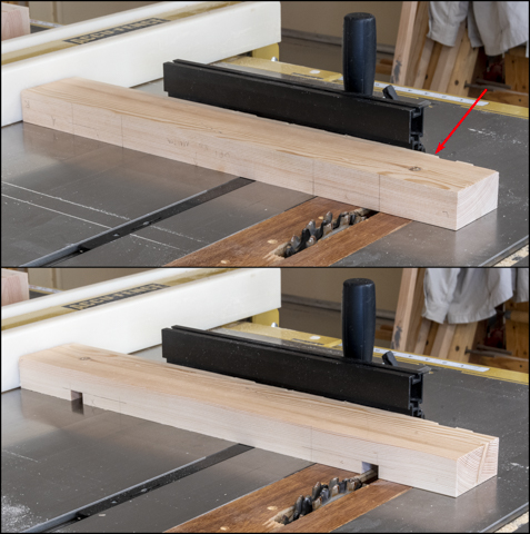
saw. In the top photo the rip fence
(white) sets the left right distance the dado’s get cut from the ends. The miter fence (black) keeps the piece
square with the blade and is used to push the piece across the blade making the
cut. Also, you can just see the backer
board next to the miter fence (red arrow) to prevent splitting when the dado
exits the cut. After the first cut the
piece is flipped end for end and the second dado is cut. The bottom photo has the first pass done.
After all the similar pieces have had their first pass
made the rip fence is moved closer to the blade and a second pass is made
expanding the dado. The top photo shows
one end with two passes. The bottom
photo shows the finished dados.
After all the dados are cut and the two halves stacked
together the mortises are clearly visible.
Next is to route a slot for a spline that the center
panel floats on. The drawings below show
the panel and splines along with where the slot gets routed. Both the top and bottom rails get routed with
the bottom rail shown.
Here is a closeup of the router table with the router bit
and fence set for the cut. Note that the
right side of the fence is really close to the bit. That’s to provide support to the wood fibers
on the exit side of the cut which reduces the splintering and chipping of the
edge. 
Here the top photo shows both halves of the base with the
groove for the spline cut clamped together ready to be glued up. In the bottom photo the pieces are lying flat
with the surfaces to be glued up.
Gluing the pieces together is next and this photo shows
the fit up in the bench vice. To make
sure the two halves align perfectly side to side there are two blocks sized to
just fit in the dados cut and inserted in the assembly. In addition, to make sure the two halves
don’t slide around while gluing and clamping there are three screws run in from
the face for alignment. They will also
provide some clamping pressure. From
here everything is taken apart, glue applied and things reassembled in the bench
vice. Afterwards the blocks are knocked
out, more clamps are added and any glue squeeze out is wiped away. The next day the clamps and screws are
removed giving me mostly completed top and bottom rails for the glider’s end
panels. 
Next Up – Finishing End Rails, End Stiles & Base Stretchers

No comments:
Post a Comment