Router Plane

Monday, February 23, 2015

Maloof Rocker - The Real Seat: Bevels, Dowels & Leg Joints

Some of  my Notes
With a basic processes needed to build the seat and legs practiced plus a couple pages of notes on things to do and not do I started on the real seat.  I made the notes as I built the mock-up to make sure I did not miss anything and because it’s pretty easy to get something out of sequence.

First order of business is to check to see if any of the seat’s rough cut pieces had moved since they were cut.  Well, three of the five had developed a bit of a twist that had to be flattened so I dragged out hand plane and set to work truing up the surfaces.  Not hard but it took half a day to get them all square, flat and to a thickness that varied less than 1/100 of an inch.  I needed the outside boards of the seat to be this accurate because the leg joints are cut from the top and bottom and what remains is the tenon of the leg joint.  If the board thickness varies so does the thickness of the tenon.   The mating piece is cut with a dado blade and does not vary once set.  End result is if the boards are different thickness then some joints will fit and some won’t.   The fix to make them go together is to modify each joint by hand.  With all the angles and arcs I really, really want to keep that to a minimum.

Once I had all the pieces ready to go I laid them out shuffling the order, flipping end to end, switching top and bottom and shifting back and forth until I got a good grain match.   The photo shows the final result.  Once the pieces are cut to width with proper bevels I will cut them to final length.
Grain Matched


This process for putting the seat blank is nearly the same as the mock-up so I will not go into a lot of detail here.  First is to mark the bevel direction then set the blade on the table saw and cut the edges on each board. 
Direction of Cut Marked


Angles Cut
Setting Saw Angle


At this point the pieces have extra width so I had room to fix any problems that might arise.  
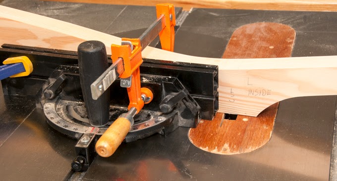
Before I cut to final size I wanted to do a test clamping to make sure I had the angles right and the outer two boards were flat, which they are.
Test Clamping
Still Flat
Next I cut boards to final width and length then clamped them all together checking to make sure everything still is in proper alignment.   

With the blank at final width I clamped the seat template to the blank then traced the seat outline and the guide line for the recessed area.  More layout followed: the dowel locations, the front leg dado then the back leg straight and angled geometry.  Unfortunately these layout lines are made with a sharp pencil resulting in thin lines that just did not show up in the photograph. 

Seat Layout Done
One change from the mock-up was the way I marked the dowels location.  In the mock-up I measured each one with the calipers.  This time I set a couple of combination squares and used them to do the layout.  If you carefully look just about 3/4 an inch off the end of the squares in the photograph you can just see a small point marking where the dowel will go.
Combination Squares Set for Marking Dowels

A dry fit and clamp with the dowels in place showed the outer boards still flat.  Not that I am paranoid about things getting out out of alignment or anything.

Still Flat? - Yep


Rear Leg Joint with Just a Smidge to Remove
Now it was time to make sawdust, drilling the dowel holes and making all the table saw cuts for the legs including the little bit of hand trimming due to intersecting angled cuts.  
All Cleaned Up
When I did the mock-up I had some problems with getting a smooth transition between the straight and angled router bits.  I felt like I needed more practice with the bits to avoid the gap problem in the actual chair.  Digging in the scrap box turned up some 2x6 material so while I had the saw set up I made four test pieces to practice the rear leg joint.


Next Up – The Real Seat: Fitting Legs & Seat Glue-up

Monday, February 16, 2015

Maloof Rocker - Seat Mockup Part 6, Add Legs & a Problem

My original plan was once I had completed the seat mockup I would start construction using the cherry.   However, I changed my mind and decided to put the seat to further use.  I had a section of the 2x6 left so decided to use it to make a set of rear legs to test the fit and procedure of making the leg-to-seat joints.  My thought was that I could also use the mockup as practice for the sculptural part of the construction.  As the 2x6 was not wide enough to make the rear legs according to the pattern I changed the design to make a low back non-rocking chair.   Here are the rough band saw cut modified back legs.
I took one of the rough legs and smoothed out the cut surfaces then double faced taped it to the other leg and used a pattern router bit to make exact duplicates.  After taking all the time to clean up and smooth the cut surfaces I am not sure if it is worth it.  The only exception may be for the reference surfaces, they are probably worth it.


The procedure for cutting and fitting the modified legs is similar to the actual ones.  There are some differences so let’s just say I spent quite a bit of time making angled dados, radiusing corners and talking to myself.  Rather than cover that here on pieces that do not match the final product I will wait until I get there in the real chair.  That said here are a couple of photos of cutting the dados.

The good news was that after all the fussing, double checking the measuring and scratching my head the joints fit just like they were designed.

When I got done with all the work on the rear legs and turning the front legs on the lathe I clamped all the pieces together including a temporary top spacer between the back legs. 

Here is where things went bad.  The front legs are supposed to be straight up and down but mine were slightly splayed out.  The rear legs did open up toward the top but it looked like not enough.  When I got out the measuring tools sure enough things were not lining up the way they were supposed to.  I finally traced the trouble to the outside boards of the seat where I had spent all the time cutting the joints.  The joints were cut right on as shown by how the legs fit into them.  The problem was that each of the outside boards that make up the seat are not level but tilted up causing the legs to rotate by a couple of degrees.  Not a lot, but a couple of degrees over a few feet is enough to mess up the size of the headrest and the form of the chair.

Now I knew what the problem was but had no idea of the why behind it.  I checked the joints between the boards to see if they were tight and that the cuts were all angled correctly, which they were.  I checked the jig I had used for drilling the dowel holes to see if it was off, which it wasn’t.  I even went back though the photos I had taken and they showed everything like it should be.  For the better part of two days I measured and checked every step and cut I had made finding no problem.  I really needed to know why this had happened so I could prevent it on the real chair.

Finally I think I know what happened.  There are a couple of differences between the mock-up and the actual piece.  First is the material, the mock-up is SPF construction lumber, a fairly soft wood while the actual chair will be cherry which is much harder.  Second, the mock-up is made from pieces just under 1 ½” thick while the real seat will be just over 1 ¾” thick.  I think that everything was fine right up to when I glued the seat together.  When I glued up the pieces and clamped them together a combination of the angled joints, softer wood, a thinner material and perhaps uneven clamping pressure caused all the joints to compress and rotate ever so slightly.  With 8 surfaces and the amount of clamping pressure I applied it would not take much to cause a 2 degree rotation.  I usually check for any bowing when I glue up a panel but did not this time.  One thing is for sure I will be checking for this problem when I do the real seat glue-up.


Next Up – The Real Seat: Bevels, Dowels & Leg Joints

Monday, February 9, 2015

Maloof Rocker - Seat Mockup Part 5, Bandsaw & Hollowing Seat


After the seat blank glue-up had set all night I removed the clamps and used the bandsaw to cut it to shape. 


Cut Out Seat Blank
Now came the time to start scooping out the contoured section of the seat.

This is my first foray on this piece out of dimensioned precise work and into the sculptural side of the project.  My only drawn layout is the outer edge of the scooped out seat and its center line.  The rest is by eye and touch.  I started with the coarse carbide disk mounted on the 4½” angle grinder.   For a bit of practice I cut a starting swath parallel to the finished edge just to get a feel for how the tool works.  After a couple of passes and with a bit of apprehension I went ahead and outlined the area to be scooped out.

Carbide Grinder
Outline of  Scooped Part of Seat
After the outline was done I could start on the bulk removal of the material and roughing the seat recess out.  Surprisingly the coarse carbide disk/grinder combo was easy to control.  The teeth are very aggressive and the disk turns at such a high rpm only a little pressure is required to remove material.   I knew that there would be a lot of shavings generated but the tool acts like a garden hose spraying shavings all over the shop!

Finished With Coarse Carbide Grinder
Once I had the seat roughed out and taken as far as I could with the coarse disk I switched to a regular 50 grit sanding disk mounted on the same angle grinder.  Once again the tool required little pressure to remove material, smooth and refine the seat shape.  It was with this tool I started to round over the front edge of the seat and finish up the majority of the shaping. 
Results From 50 Grit Disk

The next step is to move to orbital and pad sanders to remove any remaining high spots and smooth the surfaces out.  The emphasis here is not on material removal but refinement of the shape and smoothing.  Final pass is made using 120 grit paper on the pad sander along with some hand sanding.  The hand sanding is needed to ease the transitions around the inside edge.  Since this is a practice piece I stopped with the 120 grit.  For the actual seat I will probably continue on through 220 grit.  Once the face was done I flipped the seat over and cleaned up the bottom easing and smoothing the joints where the 5 seat pieces are joined.  Last step is to clean up the bandsawn outside cut edges using the disk, drum and oscillating sander.  Really, the last step is to clean up the piles of sawdust this step generates everywhere in the shop.  


Next Up - Seat Mockup Part 6, Add Legs & a Problem

Monday, February 2, 2015

Maloof Rocker - Seat Mockup Part 4, Routing & Glue-up

Well the router bit arrived today so it’s out to the shop to pick up where I left off routing the leg joints in the seat. 

The three router bits shown here (L to R) are the new straight bit and the two angled bits for top and bottom cuts.

First is to chuck up the (new) straight router bit and set the depth for 7/16”.  A couple of test cuts and minor tweaking of depth had it set up.  The front leg joint uses just this bit as the joint is square to the seat.

Dado Ready to Route

Completed Joint
Next was to use the same bit for one side of the back leg joint where it is square to the seat.

For the side of the joint that is cut at 5 degrees the two angled bits come into play.  One to cut the top and one to cut the bottom.  Process for each of the angled router bits is to chuck it up and set depth to match straight bit.  It is important that the bottom of the straight cut and angled cut match dead on.  If they don’t I run the risk of the dados that get cut in the legs not matching up with the width of the tenon.  Minor tweaking and a couple of test cuts had it dialed in.  Clamping the pieces in place and making the cut was straightforward completing the joint.


Finished Joint


What I did not realize until I was cutting with the angled router bits was that there is a slight difference in the geometry where the angle bits and the straight bit cuts come together in the corner of the joint.  If you look carefully in the corner where the two cuts meet you can see that the edges do not flow smoothly together.   This happened because I did not stop the straight bit at or just short of the corner but took it down the angled face just slightly.   This shows up in the photo below.  Well, that’s what the test piece is for, to find and correct any problems before the real piece is done.
Problem in Corner
Once all the cuts are made the seat pieces are ready to glue together.
  
Gluing up all the pieces was pretty easy since the dowels assure accurate alignment and prevented slipping when clamping.  I left the assembly set in the clamps overnight to allow the glue to cure.
Next up – Seat Mockup Part 5, Bandsaw & Hollowing Seat

Monday, January 26, 2015

Maloof Rocker - Getting & Rough Cutting Chair Wood

While waiting for the bit to arrive I worked on building a couple more of the jigs needed for construction.   This one is for making the reference cut to the back leg where it attaches to the seat so both legs are raked at the same angle.

The major milestone was a day trip with a neighbor to Albuquerque to pick up the wood I will use to build the chair.   We stopped at two places, Albuquerque Exotic Hardwoods where I was like a kid in a candy store and ended up buying a piece of Katalox (Swartzia cubensis) to be used for the feature strips in the rockers and the plugs.  I looks a lot like Wenge but the piece I got is darker and is supposed to be a little less oily making it easier to glue.  As a reference Cherry has a Janka Hardness of 950 pounds, White Oak is 1,350 pounds and the Katalox is 3,660 pounds.  Being that hard it will be interesting to see how difficult the material is to work.  Second stop was at Albuquerque Hardwood Lumber Company.  There I picked up the needed planks of rough sawn 8/4 cherry.  When I did my cut list and added a waste factor I found I needed 46.9 board feet of material.  After picking though the stack of material and doing a rough layout of the pieces on the planks the total amount I had selected came out to 46 BF.  Coming that close to my estimate made me happy. 
Rough Sawn Lumber
Once back in the shop I ran the rough sawn pieces through the planer so I could see if there were any flaws not visible while the pieces were rough.  Sure enough a few surprises became visible like knots, a couple of small pits and a crack or two.  I will say, after half a day swinging around planks 2” thick, 10” wide and 10’ long to feed through the planer I was ready to quit.
Surfaced Cherry
 Now that I could see exactly what I had I could start doing the actual layout of parts on the planks.  This is a partial layout of the back slats.
Slat Layout
Once I had a layout drawn out I rough cut the major pieces to length, width and thickness.  Fortunately only a couple of the pieces had any twist or bow that needed to be removed.   

I also checked the moisture content at the fresh cuts and found it to be around 6% indicating they are pretty dry.  The pieces are now set aside to rest and see if they are stable or are going to move.   I am hoping that they stay flat and don't twist or otherwise go wacko on me.

Rough Cut Cherry
I know the process of taking rough sawn lumber to smooth then doing an efficient layout working around flaws, rough cutting to size followed up by making them flat and square does not seem like much but it took me the better part of 3 days.

Once the router bit arrives I will be able to move on with finishing the seat joints on the Mockup.

 Next up – Seat Mockup Part 4, Routing & Glue-up

Monday, January 19, 2015

Maloof Rocker - Seat Mockup Part 3, Leg Joints

Before I get into progress on the mockup I have had a couple of questions.  First, was how long do I spend in the shop a day?  Right now it’s about 3 hours or so a day 6 days a week more or less.  Second question asked about using dowels vs biscuit joints.  This was easy for me to decide because I don’t have a biscuit joiner.  If I had one I probably would have gone with it over the dowels because I could have adjusted its fence and not had to build the 3 degree jig to drill the holes for the dowels.  Also, the biscuits would have allowed some side to side slip for alignment.

5 Degree Jig
The leg joints in the seat are constructed in two steps.  First is a cutout for the leg and second is the routing.  Together they form the seat half of the mortise and tenon joint.  The back leg cutout is first and is not a simple square notch.   Since the back legs splay out, being wider at the top than at the bottom the joint needs a 5 degree angle.  The setup is to align the crosscut fence at 85 degrees.  Well, really the first step is to make a jig so I could repeatedly and accurately set the 85 degree angle between the fence and the blade.   That required me to dig back to my high school geometry class to find the formula to calculate the base of the triangle knowing two sides and an included angle.  That took longer than I care to admit.    

Having cut the jig I used it to set the crosscut fence at the correct angle then set the blade for a 3” deep cut.   Since this cut is from the narrow end of the board I clamped the board to the fence to make sure it stayed in place.  Clamping it in place also let me keep my fingers away from the blade. 

Cutting 5 Degree Angle
The first pass through the saw was to check for proper alignment and as shown here it matched the required angle.  The second cut is right to the layout line. 

First Cut Close to the Line
Finished Cuts
The legs are mirror copies so once I made the cut on the right leg I had to re-set the fence (using the jig) for the left leg and make the same cut.  With both angled cuts made I reset the crosscut fence back square to the blade and cut the other side of the notch.  However, because of the 5 degree cut the block does not come free so there is some minor work with a hand chisel to clean up the joint.

The dado for the front leg joint is pretty simple but, it’s here that I ran into the first small problem.  The plans called for the dado to be 1½” back from the front of the seat while the DVD showed 1¾” back from the front.  Stuck and not knowing how critical this dimension was to the overall geometry and center of balance I looked up the author’s email and sent him a short note asking for clarification.    I really did not expect a reply but the very next day there was a note from Scott explaining what was going on, “The 1 3/4" measurement is as measured from the front of the RAW chunk of wood.  The 1 1/2" measurement (as depicted on the template) is obviously from the front of the template.  There is a slight difference between the raw chunk of wood and the front of the template.”  Needless to say I was impressed that he replied to me and how quick the answer came back.  Back to the shop where I marked the cut, set a stop block and with three passes using a stack set of dados made the cut.   I should explain here that the stop block registered on the back leg notch is used so the dados are exactly the same distance for the left and right side.


Cutting Front Dado


5 Degree Angle Bits
With the cutouts done the second part of the joint, the routing, could be worked on.  The front leg joint uses a straight router bit to make the ¼” wide cut on the top and bottom.  The back legs require a total of three different bits to compete.  Remember the 5 degree cut made on the table saw?  Well, two different bits are needed to make the cut to match that angle.  From the top the 5 degrees needs to slant one way and from the bottom the slant needs to go the opposite.  The square part of the cut can use a regular straight bit.  Here is where I made my first oops.  I knew I had to order the 5 degree angles bits but I had a straight bit that matched the cut width of the special 5 degree bits.  What I did not realize until I was ready to make the cut was that the diameters of the bits all had to coordinate so the interior radius at the corner of the cut would match.  This brought everything to a standstill while I ordered and waited for the appropriate straight bit to arrive.  I did go ahead and make a test set of cuts with the two angled bits on a scrap piece to see how they worked.

5 Degree Cut and Routing


Next up – Getting & Rough Cutting Chair Wood