Router Plane

Monday, April 6, 2015

Maloof Rocker - Plugging Holes, The Headrest & Drilling Slat Installation Holes

After spending all the time on the slats it is nice to move on to something a little different.   Each of the glue joints between the legs and the seat are reinforced with a couple of 2 ½” X #10 screws.  

Drilling Angled Pilot Holes for Screws
Sequence is pretty straightforward; first a ½” forstner bit is used to drill a countersink sink hole about ½” deep, then a pilot hole for the screw and finally a clearance hole just through the leg.  The only wrinkle is the pilot and clearance holes in the front leg are angled toward the center of the seat.  With the screws arranged one over the other and the scooped out seat you want the screws to bite into the meat of the seat.  Splitting the seat or having a screw come through into the scooped out area would ruin my day!

Using a Plug Cutter in Drill Press
Once the screws are driven home I need to plug the ½” countersink holes.   There are two choices for the plugs.  I can either cut a face grain plug from the cherry which would make it nearly invisible when done or go with a contrasting wood.   Typically with this chair design a contrasting wood is used, in this case I will use katalox for the plugs and the feature strips in the rockers.  Because I wanted the maximum contrast between the cherry and the katalox I decided to use an end grain plug versus a face grain plug.  The reason being when I apply a finish the end grain will darken more than the face grain.

Next is to cut the headrest to fit between the legs.  When I pulled the earmarked piece from the stack and checked for flatness I found that it had twisted a bit and needed to be flattened.  Out came the plane only this time I used a power plane and not a hand plane.  The power plane speeds the process up a lot but if you're not careful you can overshoot and take off too much material.

Once flat I ripped to rough width and got an unpleasant surprise.  A hidden flaw showed up that was really unacceptable.  A few bad words were said.  OK, it was more than a few.

Fortunately the wood gods smiled on me and when I laid the headrest template on the piece the bad part would be cut away.

Locating the center point for the hole the slats will go into on the seat is next.  To do this requires a bit of layout.  To make sure things went as planned I did a sketch and put together a sequience that I would use to do the work. 

In case you cannot read my chicken scratching here is the short version of what I did.  First, a base line is established across the seat at the back of the legs then dividers are used to equally space points along this line and a slat center line is then drawn using these points 90 degrees to the base line.  Next to arrange the slats in an arc to fit your back graduated offsets are measured along the slat center lines.  Finally, using a punch the center point of the slat is set along this line.
Punch Marks for Centering Holes for Slats


With the headrest clamped in place the dividers are again used to establish evenly spaced points along the bottom of the headrest.  Since the legs splay outward the spacing between the points is greater at the headrest than at the seat resulting in the fan shaped appearance of the slats.   Only the center slat mounting holes are square to the seat and headrest.  All the others are at graduated angles outward from the center.  To get the appropriate reference lines on the headrest for the mounting hole angles you set one end of a straight edge on the slat seat point.  The other is set at the headrest point and a line is drawn onto the headrest establishing the centerline of the slat and its mounting hole angle.
Using a Straightedge to Establish Drill Angles for Headrest Slat Mounting Holes

With the lines are in place the ½” holes in the seat can be drilled.  The lines provide a sight line you use to establish the angle you hold the drill.  This works great in theory and on my practice piece it worked like a charm.  However, when I went to drill the actual chair a problem arose.  My arms are not long enough for me to hold the drill in place and have my head so I could sight down the line on the headrest.  I had three choices:  grow longer arms, buy a ½” drill two feet long or do something else.  I opted to do something else.  The solution turned out to be clamping a straight piece of wood onto the backrest with the edge following the reference line so that is ended just short of the back of the drill.  I added a center mark at the back of the drill and then kept that in line with the edge of the wood. 
Drilling the Slat Mounting Holes

Now I could go ahead and drill the 7 holes in the seat resetting the piece of wood for each hole at its appropriate angle.


Once the seat holes are drilled that left the holes in the headrest.  They are simpler and less stressful to drill than the seat holes.  Using the drill press and shims to match the reference line angle it was easy to drill the holes at the correct angle.
Setup for Drilling Angled Holes in Headrest
Last step is to cut the arc at the top of the headrest on the bandsaw.


Next up – Sculpting the Legs

Monday, March 30, 2015

Maloof Rocker - The Back Slats

There are 7 slats that form the back of the chair and a lot of steps to take them from start to about 90% done which is where I will stop until I fit them into the chair.  The cherry slab I am using for the slats had a few “challenges” when I went to do the layout.  There are knots, holes, cracks, some wild grain and the like that I had to work around.  
Slab for Slats

 Since the slats are structural elements that end up fairly thin at each end where they are attached I also need to pay attention to how the grain runs from one end to the other.  Starting with the preliminary layout I had done earlier I worked to improve the grain alignment and slats relationship to the flaws.  It did take me the better part of an hour playing around with different layouts to finally end up with one that worked.
Final Slat Layout
 Once the layout was done I used the bandsaw to rough out the slats to smaller, more manageable pieces.
Initial Slab Breakdown
From there it’s back to the bandsaw to carefully cut just slightly wide of the pencil line completing the first of several steps toward the finished slats. 
Rough Cut Slats
Next is to use disk, oscillating drum, pad, orbital sanders plus some hand sanding to clean up the bandsawn front and back surfaces.  The finished slat is 1¼” thick but the board I cut them from is just over 1¾”.  I had two choices, either run the board through planer until I got to the right thickness or cut them out at 1¾” then resaw to the correct thickness.  I opted to cut them from the full thickness board and resaw.  My reasoning is if I came upon a hidden flaw after the first round of bandsawing to shape (remember my surprise with the seat) I had about ½” of latitude to cut down from one or both sides depending on where the flaw was.  It was fortunate that I went this route as I had a couple of instances show up that needed to be addressed.  Using a marking gauge I drew a line on each slat about a sixteenth over the 1¼” final size removing the flaw or worst looking side.  The extra sixteenth is for cleaning up the bandsaw cut on the thickness sander. 
Ready to Cut to Width
It’s back to the bandsaw using a pivot point as a guide for the cut.  I think I have used the bandsaw more on this project than just about anything I have ever made.  I could have cut the pieces on the table saw but the curved slats left a lot of blade exposed at the finish of the cut plus the piece is not all that wide and I just did not feel comfortable with my fingers less than ¾” away from the blade.  Because of the curved shape my typical push blocks and sticks did not fill me with confidence.  I like my fingers and want to keep them attached.
Cutting Slats to Width
The bandsaw leaves a roughish cut that I have to clean up.   For me the easiest way is to use the thickness sander.  With it I can easily and very accurately clean up the rough surface so that it is flat and parallel to the opposite face.
Bandsaw Cut

Once run through the thickness sander I pulled out another template that I use to outline the face of the slats.  This one is made from plastic laminate because I needed it to be flexible enough to follow the slats curves.

The front of the slat where your back rests is flat.  However, the center part of the slats back is rounded on the router table using a 5/8” radius router bit to soften and visually lighten the piece.  Because of curves the grain changes direction along the cut so to reduce the chance of chipping I cut with the rotation of the router bit or “climb cutting”.   The downside is cutting this way greatly increases the possibility of losing control during the cut and getting hurt so precautions are required to reduce the risk.  I took several light cuts, kept the hand holding the board down-stream of the bit and used a large push block to keep my upstream hand back and away from the bit if things went bad.  Several passes later the roughed out rounding was done with no problem. 

Back of Slats Routed

Cutting Top of Slat to Final Width
The top and bottom of the slats are cut down to leave roughly a ½” centered section which then transitions to the thicker center back support section.  I used the table saw and a stop block to cut the straight part.  
The remainder along with the transition is cut with the bandsaw.  Because the back is rounded I clamped a block to the side to act as a flat reference surface keeping the slat square with the bandsaw blade.  The table saw leaves a nice smooth edge however the bandsaw not so much.  To clean up the rough cut and start on the finished transition I used an oscillating drum sander.
Cutting Transition
It Almost Looks Like a Chair!
There is still quite a bit of work to be done on the slats as they are fitted into the headrest and seat which comes later.  However, for now the last step on each of the 7 pieces is to inspect all the surfaces removing any machine marks, smoothing the curves and cleaning up transitions from flat surfaces to curved surfaces.   No humps, bumps, dips or irregularities allowed.  It’s mostly by feel rather than by measuring.  A pad sander, lots of hand sanding and patience does the trick.  

Once finished I clamped them roughly where they will go in the chair just to see how they looked then set aside until later.


Next up – Plugging Holes, The Headrest & Drilling Slat Installation Holes

Monday, March 23, 2015

Maloof Rocker - Glue-up and Arms

Front & Back Legs Clamped in Place
The actual gluing of front legs to the seat is straightforward.  All that’s needed is to make sure the legs are square with the seat.   A pair of clamps above and below the seat are used to make any minor adjustments for squareness.  The back legs need a bit more since side to side clamping and front to back clamping is required.  There is also a temporary spacer that is cut at 5 degrees to match the splay of the rear legs.  When that piece is clamped in place it trues up the legs to the seat so you don’t have one leg at 6 degrees and the other at 4.

The arms are next.  I started by tracing their shape from the template then cutting them out on the bandsaw leaving the end where it connects to the back leg a little long.  That joint requires a compound cut and the setup varies depending on how the angles between the seat and legs match up.
One Arm Cut & the Other Ready for Bandsawing
After cutting the arms out I made a choice of which arm was left and which was right then moved to the disk sander to smooth the outside curve of the right arm to fit into a jig.  One of the arms can have its compound cut made using the crosscut fence while the other needs to be held in the jig.
Left Arm


Right Arm


The compound cut starts out with the blade tilted to 23 degrees and the fence square to the blade.  Once the initial cut is made and I do a test fit the adjustments begin.  I tweak both the blade and the fence to get a tight joint between the arm and the leg with the arm centered over the front leg. 
Left Arm - Initial Cut
Left Arm - Fitted
The arm is attached to the front leg using a ½” dowel.  The hole in the leg for the dowel was drilled on the lathe and then the top of the leg was cut to a 13 degree angle.  Now I need to mark the exact location of the center of the hole in the arm then drill a ½” hole at 13 degrees to get a tight joint between the arm and the leg.   Marking the hole center is easier than you might expect.  I put a dowel center finder in the hole, set the arm in place, give it a whack and the center of the hole is marked.
Dowel Finder in Place


Center Point For Drilling
Now all that I have to do is drill a hole at a 13 degree angle centered on the mark.  At first I was going to just tilt the table on the drill press but when I went to loosen it I needed a 23 mm socket to fit the clamping nut.  The way the table is constructed an adjustable wrench will not fit and guess who does not own a metric socket that size?  My alternate method, which worked just fine, is a board clamped to the table at shimmed to 13 degrees.
Jig For Drilling 13 Degree Hole in Arm


Now that I had the holes I needed a ½” dowel.  My experience with dowels purchased at the big box stores are that they are not truly round and are generally a soft wood.  Since I only need 6 dowels for the whole chair and wanted them made out of hardwood I decided to make them out of leftover pieces of cherry.   First is to cut a 5/8” square piece about 5” long and turn it to just about 1/64” oversize.
Dowel Turned 1/64" Oversize

Driving Dowel Through Die
Because trying to turn a cylinder exactly a ½” in diameter is tough I took the slightly oversize piece and drove it through a piece of steel with a ½” hole in it.  The steel acts like a die and trims the dowel to just about a thousandth over ½”.  The oversize is due to the compression and springback of the wood fibers as the blank is driven through the die.  Next is to remount in the lathe and sand slightly so I have a perfect fit.  Last is to score some grooves down the side of dowel to provide an escape for any excess glue in the joint.  I really do not want to end up building a hydraulic cylinder and split the leg apart when I clamp things together.  Cut to length they are ready to use.
Finished Dowel Ready to Cut to Length

Arms and Legs Installed
Mounting the arms to the back leg is done with a 3”x #10 screw.  Preparation requires just three steps:

1.  Drill a ½” diameter countersink hole two-thirds the way through leg.  I will fill the hole with a katalox plug later.

2.  Drill pilot hole through leg and into arm.

3.  Drill clearance hole through leg.

Once that is done assembly consists of applying glue to the dowel, the arm, clamping them in place and installing the screw.


Next-up - The Back Slats

Monday, March 16, 2015

Maloof Rocker - The Legs

Now that the seat is pretty well shaped I moved on to the legs.  The front legs came first.  For some reason the dados needed to be cut just slightly deeper.  They should have fit but with such a wide cut there is a tendency for the piece to sometimes ride up a bit giving you a slightly shallow cut.  The difference was only a couple hundredths of an inch but it was enough to keep the leg from fitting.  The fix is pretty easy using a narrow plane to shave them down a bit. 

After making that adjustment a problem in the matching the curved part of the joint needed help.  I used the pencil trick to find the high spots and worked them down a little at a time until the joint fit good and tight.


Here is the front leg template, the layout and one rough cut on the bandsaw.

Next was to mount the rough cut blank on the lathe and start turning each end to a smooth taper.  This shows one end done and ready to move on to the other end.


The front legs are attached to the rockers and arms using ½” dowels.  This requires that I drill a hole 2” deep centered on each end of the leg and in-line with the leg axis.  After some thought the best way seemed to be using the lathe.  I mounted the leg in a 3 jaw chuck, the drill bit in the tailstock and used the hand wheel to run the bit in the required 2”.


Unfortunately, when I mounted the tapered leg in the 3 jaw chuck the steel jaws dented the already turned part of the leg.
Because the wood fibers were only slightly dented and not cut the solution is to use a hot iron and a wet cloth to steam the fibers.

This causes them to swell back up to their original shape.  Once dry a quick sanding to remove the raised grain and all is well.  The front legs are now ready to glue onto the seat.


All that remains is a little work on the rear legs.  I had to cut away some of the leg’s inside face to reduce the amount of material removal during the sculpting phase.  Some of the edges then get a roundover routed on them.  To make sure I routed where I needed to and not where I didn’t I marked up the pieces.  Here are my markups after routing.  As I have said before I make notes to myself all over the pieces.  More than once it has saved my bacon.


The last bit of work is to drill a ½” hole in the bottom of the rear legs for the dowel which will be used to make the connection to the rocker.  One went just fine, straight and in-line with the center of the rear leg axis.  However, the other leg did not go quite as well.   For some reason the drill drifted slightly (less than 1/8”) off the leg axis.  Only problem that causes is when I drill the hole in the rocker I will have to match that angle.  With that, I have the legs and seat ready to glue together.


Next up - Glue-up and Arms

Monday, March 9, 2015

Maloof Rocker - The Real Seat: Bandsaw and Hollowing

This week the post is fairly short. However, the time spent in hollowing out the seat and getting it to a smooth flowing surface was not.   My description and photos of the work needed are brief because I don't know of many people that would find a lot of photos of me using a scraper and hand sanding interesting.  

After letting the seat cure overnight I took the clamps off and now am ready to get started on the sculptural shaping of the seat.  Well almost, I have to cut the seat to shape with the bandsaw but before I can do that I need to add an auxiliary table to the bandsaw because the regular table is not big enough.  

Once it was in place I cut the blank to the overall shape. 

Unfortunately, while cutting the seat to shape I got a bit of a nasty surprise.  
On the outside edge near the right rear of the seat not visible and buried within the board was a knot.  I do not know if it will get cut away as the seat is sculpted, I sure hope so.  If it does not then I will have to do something with it.

Next is to get the grinder out, mount the coarse toothed carbide wheel on it and make the sawdust fly.  The grinder runs at about 11,000 rpm and really chews through the wood.  


The cherry cuts a little slower than the pine but a light touch is all that is required to do the work.


Once I had the shape roughed out I moved on to the less coarse (50 grit) disk mounted on the grinder.  This is a little less aggressive and allows for some refinement of the shape and the creation of the smooth gentle curves at the bottom of the seat.


From there it’s on to the random orbital and pad sanders using 80 grit paper to continue smoothing and refining the seat.  The transition at the edge of the seat bottom is a small radius curve not really conducive to the use of power tools.  To refine and smooth this curve I ended up using a curved scraper plus a couple of socket wrenches out of my mechanics tool set wrapped in sandpaper. 

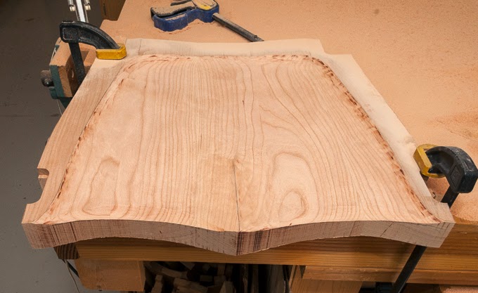
At this point the shape of the seat is pretty well set.  From here on the finer grits are used not so much to shape as to remove scratches and prepare the surface for finishing.  I worked my way to 220 grit then stopped, for now.   You would not believe the pile of sawdust I ended up with, just on the workbench that was generated in sculpting the seat.

The next to last bit of work on the seat in this step is to route a ¾” radius on the bottom edge of three sides.  The radius is stopped short of the leg joints to allow for sculpting of the transition between the seat and the legs. 

As you may guess the final part of this step is to take a couple of hours cleaning up all the sawdust that gets EVERYWHERE!!

Next Up – The Legs