
Next is to rip the blanks into six pieces that form the
blanks for the actual segments. This
starts by ripping the piece along the glue joint between the two cherry pieces
on the table saw. The red arrow in the
bottom photo points to that joint.
Using the chop saw with a stop block for accuracy each
half of the just cut blank (red arrow) gets cut into three pieces. Just to the left of the blank is a
pencil. I use its eraser end to hold the
blank down when the cut is being made in case somethings wrong my fingers are
away from the blade. The three cut
pieces are shown toward the bottom of the photo in front of the uncut blank.
Twelve of these individual blocks will make up each of the four rings used in
the bowl’s major feature band.
Using the pencil as a safety device to keep my fingers
away from the blade turned out to be a really, really good idea since when I
was cutting the 5th block somehow the piece got awry getting caught up in the
blade, demolishing it and ripping the pencil out of my hand. Fortunately, all that happened to me was a
short-term slight numbness in my hand from the force when the pencil got yanked
away. It all happened so fast that I
don’t really know what went wrong but my best guess is the shim used on the
right side of the blade to level the blank somehow caused the piece to pinch
against the blade causing the catch. The
result is the larger piece got thrown out to the right a few feet with the
small piece nowhere to be seen. I did
find it about 15’ away from the saw when I was sweeping up at the end of the
day. After removing the shim there was
no problem in making the rest of the cuts although I did have to reset the stop
block as the impact moved it. 

The base of the bowl is next. A typical ring is made up of twelve segments
open in the center like the drawing on the top left. That does not work for the bottom layer since
a solid bottom is needed. One could use
a solid piece of wood here but due to differential expansion and contraction
caused by changes in humidity either the rings or the base would probably crack
and that’s not acceptable. Using a ring
like the one on the top right is possible but does come with its own
problems. I have used a hybrid ring with
a small 1” diameter tapered plug in the center and that helps but don’t like
the aesthetics. I have gotten around
that problem with the solution shown in the bottom drawing. The blue piece is a three-layer shop made
piece of oak plywood 3/16” thick. It
floats in a slot made in the bottom layer and capped with the next layer
up. The left half of the bottom drawing
is before turning and the right side is a rough idea of what the finished
turning will look like.
When selecting a piece of oak for the plywood I wanted a
stable piece so sorted through my shorts until I found a piece that did not
have the growth rings running parallel to the long face. My first preference would be one where the
growth rings are 90 degrees to the long face or quarter sawn. The bottom photo is of the one selected and
since only the left two thirds of the left side of the piece will be used most
of the rings are at a 45 degree or so angle to the face which should give me a
pretty stable finished part.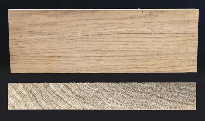
The plywood will be made from three layers each 1/16”
thick. To make the layers the selected
piece of oak has a thin slice just over 1/16” cut off using the bandsaw. The setup is shown in the two photos below.
To remove the bandsaw blade cut roughness out the thin
piece gets run through the thickness sander.
To support the piece as it’s run through the sander a ¼” thick carrier
is used. The top photo shows it ready to
go through the sander. I have marked the
bandsawn surface with a pencil to gauge when it’s smooth as it’s run though the
sander. The bottom photo is a dial
caliper showing the piece being just a tiny bit under 1/16” thick.
After cutting three layers of the oak to size they are
glued up with the middle layer’s grain running 90 degrees to the top and bottom
layers. The top photo shows how they
will get stacked and the bottom photo is the setup for gluing.
Once the layers are glued and aligned, they get taped to
a backer board that has a melamine covering the glue will not stick to. This assembly is set in the bench vice,
another backer board added and the vice tightened. Last is to add two C-clamps to securely clamp
the top edge. The piece is left
overnight for the glue to cure. 
With the floating insert glue curing I can select
material to make the bottom two segmented layers. The first step is to refer to a spreadsheet
(below) that has all the information about the segments size for each
ring. The blue numbers (radius, width
and thickness) are those that I entered and the rest are calculated based on
them.
In the left drawing below the green is the finished
profile of the bowl and the grey areas are a buffer for small changes in the
design as it gets turned on the lathe.
The right side shows a cross section and sizes of each of the individual
segments that make up the layers. The
dimensions that go into the spreadsheet come from this drawing.
Next Up – Making and Mounting the Bottom Layer


