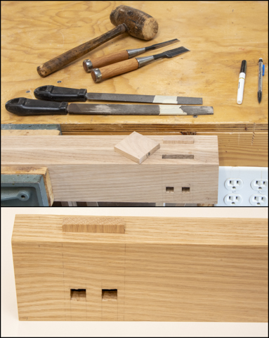
Going through the leftover cutoffs I came across these two
that could be cut down and made into the parts.
Process for making the blanks is to rip these two cutoffs into 4 pieces about 2” wide or just slightly wider than the widest tenon. Next is to rip the thickness to 7/16” on the
bandsaw then run them through the thickness sander until they were just a few
thousands of an inch too thick to go in the mortise. Near the bottom of the photo you can see the
pine test piece made into faux tenon.
It’s left over from the spacers I used when cutting the square peg
hole.
Using a rasp, file and chisels I smoothed the inner faces
of the mortise until the tenon blank fit snugly. Then after it was cut to length on the chop saw I
labeled the hidden end to match the leg.
I could stop here but thought that the sharp corner of
the tenon is right at toe level and it would only be a matter of time before
somebody whacked their big toe on it, probably me. The corner also presents a place that could
be easily chipped. To get around both
problems I decided to add a small ¼” radius to the corners. Below is the template I made for layout and
the two different size faux tenons that need to be made. I took the time to make the template as there
are 16 tenons to make. One interesting
thing about the template is the radiuses on it are 1/32” larger than the finished
radius. That’s to take care of the
offset introduced due to the thickness of the .5mm mechanical pencil I use.
Here is what the assembled leg, bottom rail and faux
tenon look like.
The next set of parts I am going to start on are the side
spacers. They are the pieces that when
applied to the plywood sides will give the impression of a frame and panel
assembly.
Back in post 5 Bandsawing, a Revision & Work on Doors
I made the blanks and left them to set to see if they were stable. Because the pieces were all flatsawn I
thought that they would probably cup at least a little as they adjust to their
new thickness. Well, they did not
disappoint me as nearly all of them had developed a little bit of cup. They were flattened by running them through
the thickness sander then set aside once more while I worked on the
templates.
Cutting the oak plywood back is next but first I needed
to print out the cut list. Here it is
showing both the ¼” and ¾” thick pieces.
The large piece on the left is the ¼” back. The rest are ¾” thick; the long ones in the
center are the sides, the group of three on the right are the shelves and the
single one in the lower right is the bottom.
Here it is after making the cut. You can see the stands that provided the
support. They are set wide enough apart
that I could walk through them while making the cut. With one edge cut I rotated the piece end for end and made a second cut to the final width which removed that edges dings and dents.
Cutting to length is more involved that ripping to
width. The maximum width I can set my
table saw fence for is 50”. Seeing as I
need a piece just over 72” long that’s a problem. What I can do move the fence to the left of
the blade and cut off the waste. That
works except that I can’t cut more than about 12” off with the straight edge
attached. As one of the plywood sheets
had a split in the veneer on the “B” side near each end it was not such a big
deal since I needed to trim some off each end anyway. My setup included moving the roller stands to
the side positioning them so at least one was supporting the end at all
times. I also changed my straight edge
from the 8’ level to a 4’ level since the shorter level is narrower and I could
pick up another inch or so in cut width.
The last consideration in setting the fence is to measure
to the outside of the blade rather than measuring to the inside. That’s because what we want is the piece
being cutoff and the thickness of the blade has to be taken into account. With these two cuts and I had the back to
size.
The last work on the plywood back piece is to bevel the edges
to help me ease the panel into the grooves in the legs and rails. That’s easily done with a small block
plane. The top photo is before and
bottom one shows the beveled edge.
Once that was done, I did a test assembly to see if all
the measuring and careful work paid off.
Well everything just fit together fine and the assemblies look
great. After just clamping things
together I checked the diagonals to see if the panels were square and they were
less than 1/16” off. That’s good news as
they should be right on when I do the final assembly and glue-up.
Next up – Stain Samples, Cutting ¾” - 4’x8’ Plywood Sheets
& Testing


No comments:
Post a Comment